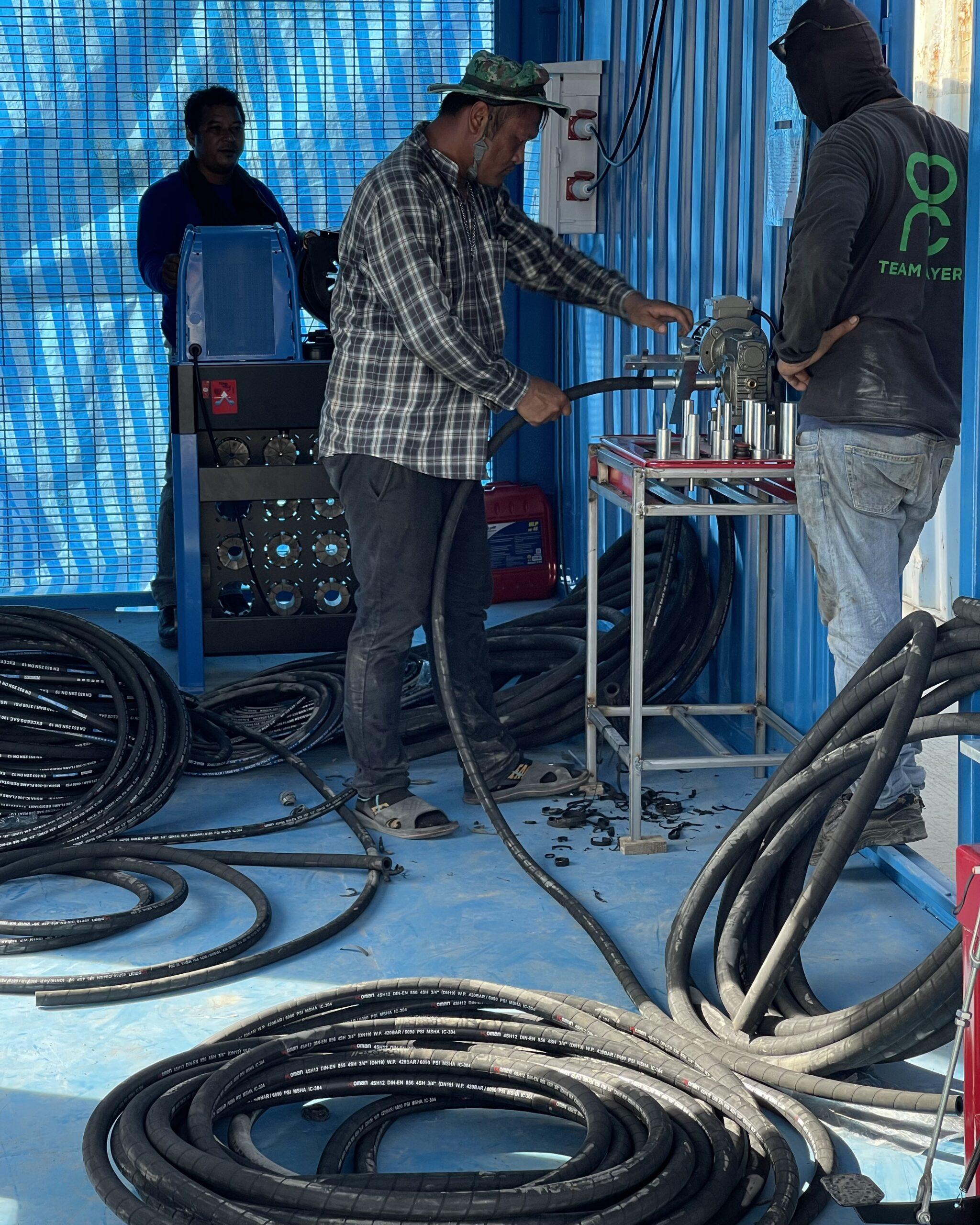
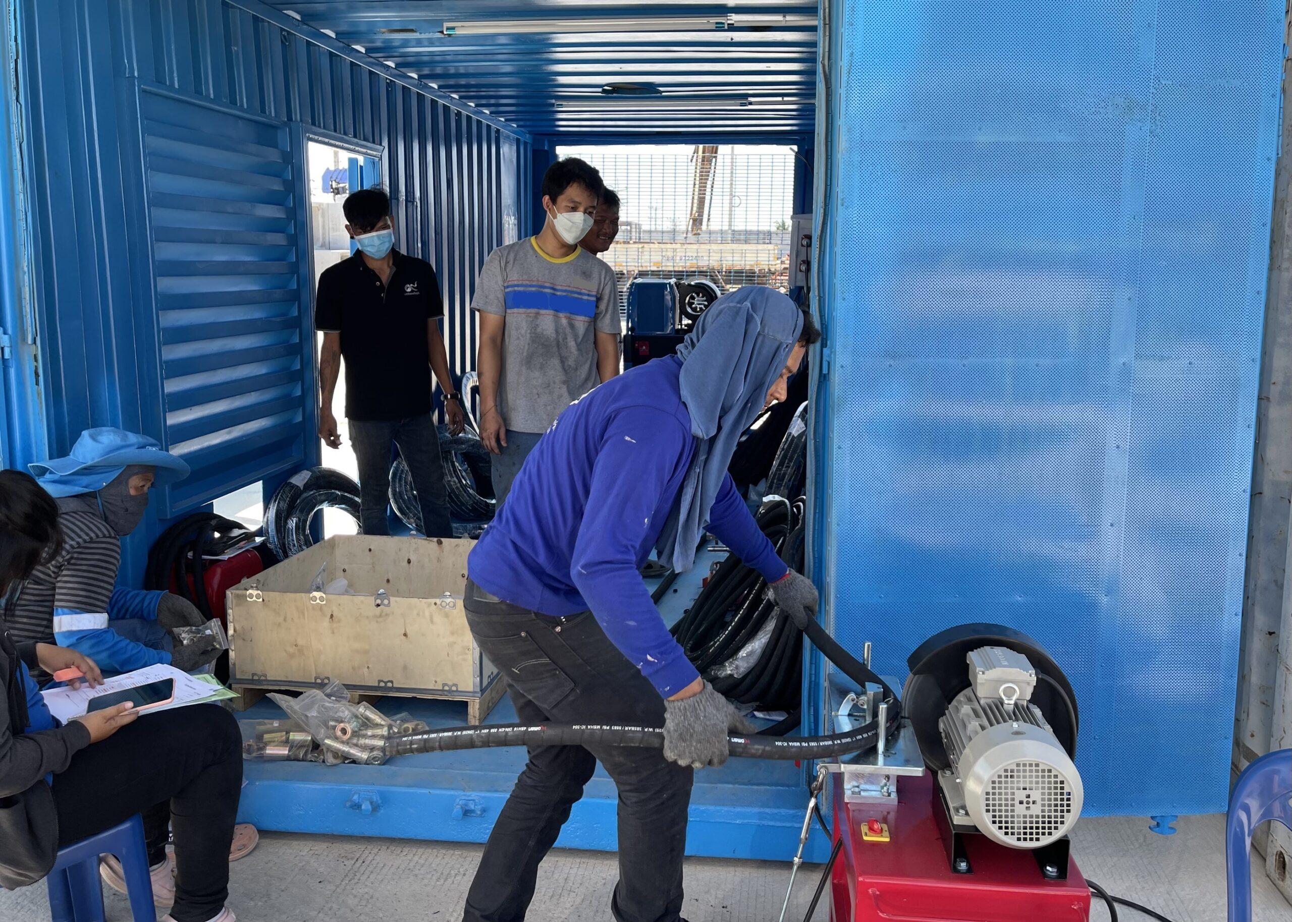
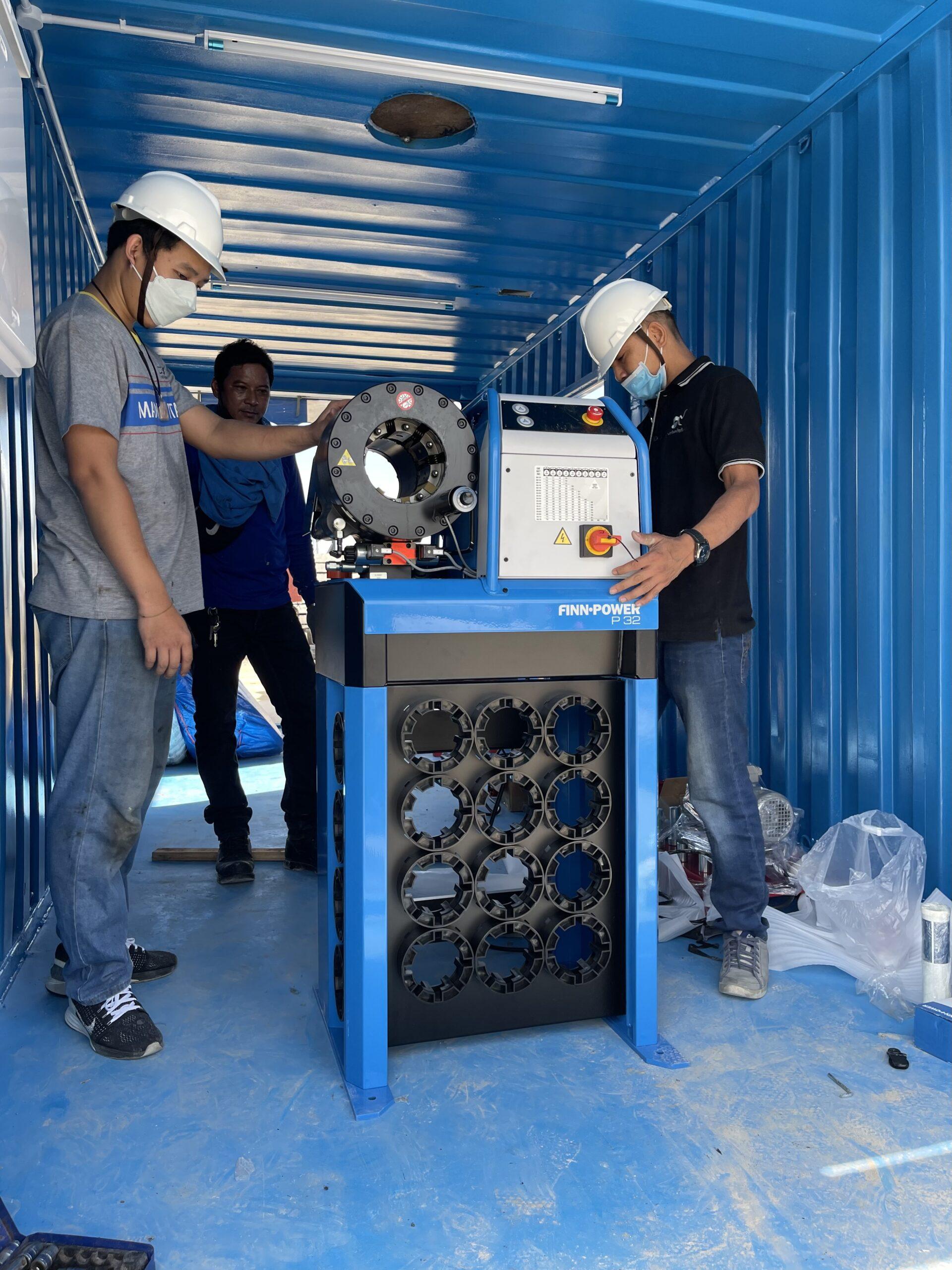
The installation of the Hydraulic hose assembly machines , HYD hose crimping machine , HYD hose skiving machine , HYD hose cutting machine at the Hose Assembly Workshop, in-house training for the theory training and practical training
Subject : Training on Hose Assembly Parts , Hose Workshop
** Production work, spare parts, hydraulic hose assembly Job. Recondition Work**
As you wish to give the company To train your staff (In-House training) on Hose Parts in order to increase their experience, expertise and confidence in offering Hose Parts to your customers.
The company is very pleased On the day that I will come to serve you as well as propose topics to train your employees The details are as follows :-
Training course “Hose Parts Training Course”
1) Theory of Hose Assembly Manufacturing Techniques
2) Hose Selection
3) Fitting Selection
4) Hose Assembly Procedures
5) Installation Procedures (Hose Installation Procedures)
6) Safety Issues
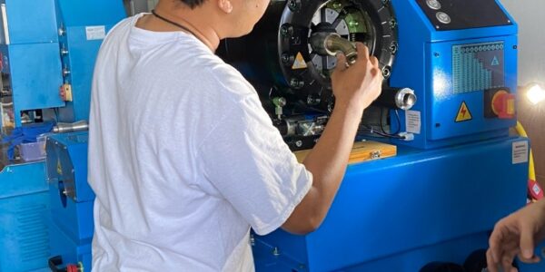
7) Setting up the hydraulic hose crimping machine.
8) Teach you how to use a hydraulic hose crimping machine.
9) The measurement of HYD hose Assembly Parts
etc.
The Training for HYD Hose Assembling at hose assembly workshop.
The training was as follows :-
Hydraulic Hose Assembling Training for 2 and 4 plies reinforcement with high pressure fittings. measurement
Training courses mentioned above It takes about 120 minutes and at the end of the lecture It will be allowed to ask questions. by the speakers of the company happy to answer questions and consult any problems with Hose Parts.
The Training for HYD Hose Assembling at hose assembly workshop.
The training was as follows :-
Hydraulic Hose Assembling Training for 2 and 4 plies reinforcement with high pressure fittings.
Preparation of Chart Board for inspection attached at the hose assembly workshop and repair center , chart board, hydraulic lines and fittings.
The installation of the Hydraulic hose assembly machines , HYD hose crimping machine , HYD hose skiving machine , HYD hose cutting machine at the Hose Assembly Workshop, in-house training for the theory training and practical training
Subject : Training on Hose Assembly Parts , Hose Workshop
** Production work, spare parts, hydraulic hose assembly Job. Recondition Work**
As you wish to give the company To train your staff (In-House training) on Hose Parts in order to increase their experience, expertise and confidence in offering Hose Parts to your customers.
The company is very pleased On the day that I will come to serve you as well as propose topics to train your employees The details are as follows :-
Training course “Hose Parts Training Course”
1) Theory of Hose Assembly Manufacturing Techniques
2) Hose Selection
3) Fitting Selection
4) Hose Assembly Procedures
5) Installation Procedures (Hose Installation Procedures)
6) Safety Issues
7) Setting up the hydraulic hose crimping machine.
8) Teach you how to use a hydraulic hose crimping machine.
9) The measurement of HYD hose Assembly Parts
etc.
The Training for HYD Hose Assembling at hose assembly workshop.
The training was as follows :-
Hydraulic Hose Assembling Training for 2 and 4 plies reinforcement with high pressure fittings. measurement
Training courses mentioned above It takes about 120 minutes and at the end of the lecture It will be allowed to ask questions. by the speakers of the company happy to answer questions and consult any problems with Hose Parts.
The Training for HYD Hose Assembling at hose assembly workshop.
The training was as follows :-
Hydraulic Hose Assembling Training for 2 and 4 plies reinforcement with high pressure fittings.
วัดเส้นผ่านศูนย์กลางเกลียวด้วย Id / OD Caliper ใช้เกจวัดระยะเกลียวเพื่อกำหนดจำนวนเกลียวต่อนิ้วหรือระยะห่างระหว่างเกลียวในการเชื่อมต่อแบบเมตริก
แยกแยะ พอร์ตของไหล และ ตัวเชื่อมต่อ ยังไง แนะนำ ถึง ระบบเกลียว อเมริกัน, อังกฤษ, ญี่ปุ่น, เยอรมัน (DIN เมตริก) และ ISO การเชื่อมต่อ
How to Identify Fluid Ports and Connectors.
A guide to North American, British, Japanese, German (DIN metric), and ISO connections
How to measure threads
Measure the thread diameter with an I.D./O.D. caliper. When comparing your measurements with the dimensions shown in this guide, remember threads can become worn and distorted from use. Your measurements may not match exactly to the figures shown in our tables.
Use a thread pitch gauge to determine the number of threads per inch or the distance between threads in metric connections. Place the gauge on the threads until the fit is snug. Match your measurements with the tables in this guide.
How to measure four-bolt flanges
First measure the port hole diameter using a caliper. Next, measure the longest bolt hole spacing from center to center or measure the flange head diameter.Dash numbersMost fluid pipe and tube sizes in the United States are identified by dash numbers, abbreviations that make ordering components easier.
Dash numbers are commonly expressed as the numerator of a fraction where the denominator is always 16. For example, a -04 port or connector is 4/16 or 1/4 inch. Dash numbers are usually nominal (in name only).Metric threads are actual size and do not use dash numbers. For example, M16x1.5 = 16 mm thread O.D. with 1.5 mm between each thread i
Amercial Dryseal Pipe Threads
National Pipe Tapered Fuel (NPTF)
This connection is still widely used in fluid power systems, even though it is not recommended by the National Fluid Power Association (NFPA) for use in hydraulic applications. The thread is tapered and the seal takes place by deformation of the threads.
NPTF Thread Tip: Measure the thread diameter and subtract one quarter inch to find the nominal pipe size.
NPTF thread
National Pipe Straight Mechanical (NPSM)
This connection is sometimes used in fluid power systems. The female half has a straight thread and an inverted 30° seat. The male half has a straight thread and a 30° internal chamfer. The 30° seat of the female seals against the chamfer on the male. The threads hold the connection mechanically.A properly chamfered NPTF male (page 2) will also seal with a NPSM female.
NPSM thread
JIC 37° Flare
SAE J514
Originally named for the now-defunt Joint Industrial Commission (JIC), this connection is very common in fluid power systems. Both the male and female halves of this connection have 37° seats. The seal takes place by establishing a line of contact between the male flare and the female cone seat. The threads hold the connection mechanically. This connection is also commonly used with flared tubing (not pictured)
JIC thread
SAE 45° Flare
SAE J512
This connection is very common in refrigeration, automotive and truck piping systems. The connectors are frequently made of brass. Both the male and female halves of this connection have 45° seats. The seal takes place between the male flare and the female cone seat. The threads hold the connection mechanically.
This connection is also commonly used with flared tubing (not pictured).
SAE 45 degree Flare
SAE Straight Thread O-Ring (ORB)
SAE J1926-1 and ISO 11296-1
Caution: In sizes – 02, – 03, – 04, 05, – 08 and – 10, the threads of the SAE 37° flare and SAE 45° flare are the same. However, the sealing surface angles are not the same.
Conforms to MS16142, UN/UNF Threads
This port connection (sometimes called O-Ring Boss) is recommended for optimum leakage control in medium and high pressure hydraulic systems. The male connector has a straight thread and an O-ring. The female port has a straight thread, a machined surface (minimal spotface) and a chamfer to accept the O-ring. The seal takes place by compressing the O-ring into the chamfer. The threads hold the connection mechanically.
ORB thread
Flareless Compression.
SAE J514
The male connector has parallel threads and a 24° seat. The female half of this connection incorporates a bite-type ferrule/sleeve used in conjunction with a tube and a female nut. When the nut is tightened, the seal is made between the sleeve and the 24° seat. A seal is also made between the sleeve and the tubing. The threads hold the connection mechanically
Flare less Compression thread
O-Ring Face Seal (ORFS)
SAE J1453
This connection offers the very best leakage control available today. The male connector has a straight thread and O-ring in the face. The female has a straight thread and a machined flat face. The seal takes place by compressing the O-ring onto the flat face of the female, similar to a flange type fitting. The threads hold the connection mechanically.
ORFS thread
Inverted Flare
SAE J512
This connection is frequently used in automotive systems. The male connector can either be a 45° flare in the tube fitting form or a 42° seat in the machined adapter form. The female has a straight thread with a 42° inverted flare. The seal takes place on the flared surfaces. The threads hold the connection mechanically.
Inverted Flare thread
Four-Bolt Flange
SAE J518 and ISO 6162
Interchangeable with DIN 20066 and JIS B 8363, except for the bolt sizes.
This connection is commonly used worldwide to connect larger size hose and tubing (1/2″ to 3″) in fluid power systems. An O-ring, inserted into a ring groove in the flange head, seals on a smooth faced female port, and is held in place by two clamp halves and four bolts in rectangular pattern.
ISO 6162 / SAE J518 flanges come in two pressure classes: the standard series Code 61 and the high pressure (6,000 psi) Code 62.
Four-Bolt Flanges
Note: CAT thick flanges have a flange thickness of 0.56″ (all sizes) to interchange with Caterpillar® split flanges. All other CAT flange dimensions are identical to Code 62.
O-Ring Pilot Threads
This connection, sometimes known as Beadlock, is common to air condition- ing systems, both in vehicle and commercial applications. Both the male and female halves of the connection have a pilot, either long or short. The seal takes place by compressing an O-ring adjacent to the bead of the tube. The threads hold the connection mechanically.
O-Ring Pilot Threads
British Standard Pipe
British Standard Pipe Parallel (BSPP)
The BSPP (parallel) male connection is similar to, but not interchangeable with, the American NPSM male. The thread pitches are different in most sizes. The female swivel BSPP has a tapered nose, which seals on the cone seat of the male.
BSPP thread
British Standard Pipe threads are somtimes identified as “G” (for parallel threads) or “R” (for tapered threads) followed by a fractional dimension.
Example: 1⁄2– 14 BSPP may be expressed as G 1⁄2
British Standard Pipe Tapered (BSPT)
The BSPT (tapered) male connector is similar to American NPTF, but the thread pitches are different in most sizes. The thread form and diameters are close, but not identical. Sealing is accomplished by distorting the threads. A properly chamfered BSPT male will also seal with a BSPP female swivel.
BSPT thread
Flat Face Port with BSPP Threads
ISO 1179-1
DIN 3852, Part 2
Parallel threads seal using various sealing rings or washers, such as O-rings, bonded seals or metal to metal seals. The female port has a machined flat surface (spotface) which the male seals against.
Please see the ISO 228-1 “G” or BSPP thread dimensions.
BSPP Flat Face
Flat Face Port with Metric Threads
ISO 9974-1
DIN 3852, Part 1
This connecion is similar to ISO 1179-1, except for the metric threads. The fittings have parallel threads and seal using various sealing rings, washers or metal to metal seals.
For illustration, please see the diagrams of ISO 1179-1 on the facing page.
ISO 261 “M” Metric Threads
Metric Thread Flat FaceMetric Flat Face
Metric Port and Stud Ends
ISO 6149
ISO 261 Metric Threads and O-Ring Seal
This port connection is similar to the SAE J1926-1 Straight Thread O-Ring , except for the metric threads. The male connector has a straight metric thread and an O-ring. The female port has a straight metric thread, a machined surface(minimum spotface) and a chamfer to accept the O-ring. The seal is created by compressing the O-ring into the chamfer, and the threads hold the connection mechanically.
M14x1.5 is recommended for diagnostic port applications.
Metric 60° Cone
DIN 7631
This thread is frequently used in hydraulic systems. The male connector has a straight metric thread and a 60° (included angle) recessed cone. The female has a straight thread and a tapered nose/globeseal seat. The seal takes place between the cone of the male and nose of the tapered nose/globeseal flareless swivel. The threads hold the connection mechanically.
60 degree cone seat
Metric Tube Compression / 24° Cone.
DIN 2353
This metric system consists of one male and three female connectors, all of which have straight metric threads. Sealing takes place between the 24° seat in the male connector and the respective sealing areas in the female connectors.
Metric Tube Compression / 24° Cone
DIN 2353 L and DIN 2353 S
Metric tube compression fittings include two connections, the DIN 2353 L “light” series and the DIN 2353 S “heavy” series. The thread dimensions and tube sizes are different for each series.
Metric tube compression
Japanese Industrial Standard
JIS 30° Flare
The JIS 30° flare connection is similar to the American JIC 37° flare (page 4), except for the 30° seat angle and the JIS B 0202 thread dimensions, which are the same as BSPP.
JIS 30 degree flare
Komatsu 30° Flare
JIS Metric
Used extensively on Komatsu equipment, this connection has a 30° seat and parallel metric threads. Also referred to as JIS Metric, Komatsu fittings are sometimes confused with JIS 30° flare which has BSPP thread dimensions.
การแปรรูป วุ้นน้ำมะพร้าว(Nata De Coco) เพื่อการทำแยม โยเกริต์ และ การส่งออก เช่น
a. แยมวุ้นน้ำมะพร้าว(Nata De Coco Jam) นำไปส่งเข้าโรงงาน Ducth Mill, Foremost, Nestles หรือBetagent ฯลฯ
b. ทำ Nata De Coco in 20% Brix syryp อัดกระป๋องส่งออก ไปญี่ปุ่น (ทุกๆปีจะมีคนญี่ปุ่นเข้ามากว้านซื้อ เพราะถือว่าเป็นอาหารสุขภาพ พัฒนามาจาก”เห็ดรัสเซีย” เป็นต้น
หนังสือที่เขย่าโลกแห่งการเงิน! JP Morgan ประกาศ“ Rich Dad Poor Dad, a ต้องอ่าน A Must read สำหรับเศรษฐี – วารสาร WALL STREET
เหตุผลหลักที่ผู้คนต้องดิ้นรนทางการเงินก็เพราะพวกเขาใช้เวลาหลายปีในโรงเรียน แต่ไม่ได้เรียนรู้เรื่องเงิน ผลที่ได้คือคนเรียนรู้ที่จะทำงานเพื่อเงิน…. แต่ไม่เคยเรียนรู้ที่จะมีเงินทำงานให้พวกเขา – Robert T. Kiyoaski
A hydraulic system contains and confines a liquid in such a way that it uses the laws governing liquids to transmit power and do work. This chapter describes some basic systems and discusses components of a hydraulic system that store and condition the fluid. The oil reservoir (sump or tank) usually serves as a storehouse and a fluid conditioner. Filters, strainers, and magnetic plugs condition the fluid by removing harmful impurities that could clog passages and damage parts. Heat exchanges or coolers often are used to keep the oil temperature within safe limits and prevent deterioration of the oil. Accumulators, though technically sources of stored energy, act as fluid storehouses. 2-1. Basic Systems. The advantages of hydraulic systems over other methods of power transmission are—
• Simpler design. In most cases, a few pre-engineered components will replace complicated
mechanical linkages.
• Flexibility. Hydraulic components can be located with considerable flexibility. Pipes
and hoses in place of mechanical elements virtually eliminate location problems.
• Smoothness. Hydraulic systems are smooth and quiet in operation. Vibration is kept
to a minimum.
• Control. Control of a wide range of speed and forces is easily possible.
• Cost. High efficiency with minimum friction loss keeps the cost of a power transmission
at a minimum.
• Overload protection. Automatic valves guard the system against a breakdown from
overloading.
The main disadvantage of a hydraulic system is maintaining the precision parts when they are exposed to bad climates and dirty atmospheres. Protection against rust, corrosion, dirt, oil deterioration, and other adverse environment is very important. The following paragraphs discuss several basic hydraulic systems. a. Hydraulic Jack.In this system (Figure 2-1, page 2-2), a reservoir and a system of valves has been added to Pascal’s hydraulic lever to stroke a small cylinder or pump continuously and raise a large piston or an actuator a notch with each stroke. Diagram A shows an intake stroke. An outlet check valve closes by pressure under a load, and an inlet check valve opens so that liquid from the reservoir fills the pumping chamber. Diagram B shows the pump stroking downward. An inlet check valve closes by pressure and an outlet valve opens. More liquid is pumped under a large piston to raise it. To lower a load, a third valve (needle valve) opens, which opens an area under a large piston to the reservoir. The load then pushes the piston down and forces the liquid into the reservoir. b. Motor-Reversing System. Figure 2-2, page 2-3, shows a power-driven pump operating a reversible rotary motor. A reversing valve directs fluid to either side of the motor and back to the reservoir. A relief valve protects the system against excess pressure and can bypass pump output to the reservoir, if pressure rises too high. c. Open-Center System.In this system, a control-valve spool must be open in the center to allow pump flow to pass through the valve and return to the reservoir. Figure 2-3, page 2-4, shows this system in the neutral position. To operate several functions simultaneously, an open-center system must have the correct connections, which are discussed below. An open-center system is efficient on single functions but is limited with multiple functions. (1) Series Connection. Figure 2-4, page 2-4, shows an open-center system with a series connection. Oil from a pump is routed to the three control valves in series. The return from the first valve is routed to the inlet of the second, and so on. In neutral, the oil passes through the valves in series and returns to the reservoir, as the arrows indicate. When a control valve is operated, the incoming oil is diverted to the cylinder that the valve serves. Return liquid from the cylinder is directed through the return line and on to the next valve.
This system is satisfactory as long as only one valve is operating at a time. When this happens, the full output of the pump at full system pressure is available to that function. However, if more than one valve is operating, the total of the pressures required for each function cannot exceed the system’s relief setting.
Figure 2-1. Hydraulic jack
Figure 2-2. Motor-reversing system
Figure 2-3. Open-center system
Figure 2-4. Open-center system with a series connection
(2) Series/Parallel Connection. Figure 2-5 shows a variation on the series-connected type. Oil from the pump is routed through the control valves in series, as well as in parallel. The valves are sometimes stacked to allow for extra passages. In neutral, a liquid passes through the valves in series, as the arrows indicate. However, when any valve is operating, the return is closed and the oil is available to all the valves through the parallel connection.
When two or more valves are operated at once, the cylinder that needs the least pressure will operate first, then the cylinder with the next least, and so on. This ability to operate two or more valves simultaneously is an advantage over the series connection. (3) Flow Divider. Figure 2-6, page 2-6, shows an open-center system with a flow divider. A flow divider takes the volume of oil from a pump and divides it between two functions. For example, a flow divider might be designed to open the left side first in case both control valves were actuated simultaneously. Or, it might divide the oil to both sides, equally or by percentage. With this system, a pump must be large enough to operate all the functions simultaneously. It must also supply all the liquid at the maximum pressure of the highest function, meaning large amounts of HP are wasted when operating only one control valve. d. Closed-Center System. In this system, a pump can rest when the oil is not required to operate a function. This means that a control valve is closed in the center, stopping the flow of the oil from the pump. Figure 2-7, page 2-6, shows a closed-center system. To operate several functions simultaneously, a closed-center system have the following connections: (1) Fixed-Displacement Pump and Accumulator. Figure 2-8, page 2-7, shows a closed center system. In this system, a pump of small but constant volume charges an accumulator.
Figure 2-5. Open-center system with a series/parallel connection
Figure 2-6. Open-center system with a flow divider
Figure 2-7. Closed-center system
Figure 2-8. Fixed-displacement pump and accumulator
When an accumulator is charged to full pressure, an unloading valve diverts the pump flow back to a reservoir. A check valve traps the pressured oil in the circuit.
When a control valve is operated, an accumulator discharges its oil and actuates a cylinder. As pressure begins to drop, an unloading valve directs the pump flow to an accumulator to recharge the flow. This system, using a small capacity pump, is effective when operating oil is needed only for a short time. However, when the functions need a lot of oil for longer periods, an accumulator system cannot handle it unless the accumulator is very large. (2) Variable-Displacement Pump. Figure 2-9, page 2-8, shows a closed-center system with a variable-displacement pump in the neutral mode. When in neutral, oil is pumped until the pressure rises to a predetermined level. A pressure-regulating valve allows the pump to shut off by itself and maintain this pressure to the valve. When the control valve is operating, oil is diverted from the pump to the bottom of a cylinder. The drop in pressure caused by connecting the pump’s pressure line to the bottom of the cylinder causes the pump to go back to work, pumping oil to the bottom of the piston and raising the load.
When the valve moves, the top of the piston connects to a return line, which allows the return oil that was forced from the piston to return to the reservoir or pump. When the valve returns to neutral, oil is trapped on both sides of the cylinder, and the pressure passage from the pump is dead-ended. After this sequence, the pump rests. Moving the spool in the downward position directs oil to the top of the piston, moving the load downward. The oil from the bottom of the piston is sent into the return line.
Figure 2-10, page 2-8, shows this closed-center system with a charging pump, which pumps oil from the reservoir to the variable-displacement pump. The charging pump supplies only the makeup oil required in a system and provides some inlet pressure to make a variabledisplacement pump more efficient. The return oil from a system’s functions is sent directly to the inlet of a variable-displacement pump.
Figure 2-9. Variable-displacement pump
Figure 2-10. Closed-center system with charging pump
Because today’s machines need more hydraulic power, a closed-center system is more advantageous. For example, on a tractor, oil may be required for power steering, power brakes, remote cylinders, three-point hitches, loaders, and other mounted equipment. In most cases, each function requires a different quantity of oil. With a closed-center system, the quantity of oil to each function can be controlled by line or valve size or by orificing with less heat build up when compared to the flow dividers necessary in a comparable open-center system. Other advantages of a closed-center system are as follows:
It does not require relief valves because the pump simply shuts off by itself when standby pressure is reached. The prevents heat buildup in systems where relief pressure is frequently reached.
The size of the lines, valves, and cylinders can be tailored to the flow requirements of each function.
Reserve flow is available, by using a larger pump, to ensure full hydraulic speed at low engine revolutions per minute (rpm). More functions can be served.
It is more efficient on functions such as brakes, which require force but very little piston movement. By holding the valve open, standby pressure is constantly applied to the brake piston with no efficiency loss because the pump has returned to standby.


 NPTF thread
 NPSM thread
 JIC thread
 SAE 45 degree Flare
 ORB thread
 Flare less Compression thread
 ORFS thread
 Inverted Flare thread
 Four-Bolt Flanges
 O-Ring Pilot Threads
 BSPP thread
 BSPT thread
 BSPP Flat Face
 Metric Thread Flat Face
 Metric Flat Face
 60 degree cone seat
 Metric Tube Compression / 24° Cone
 Metric tube compression
 JIS 30 degree flare


 ชุดประกอบท่อไฮโดรลิค แตกรั่ว Bursted
 การยึดติดกับการปิดใหม่โดยไม่ได้ตั้งใจโดยบอลวาล์วแบบล็อคได้
 อุปกรณ์ป้องกันส่วนบุคคลสำหรับการเปลี่ยนถ่ายน้ำมันเครื่องการขนถ่ายของเหลวไฮดรอลิก
 การปกป้องผิวหนังและสุขอนามัยการขนถ่ายของเหลวไฮดรอลิก
 Trolley สำหรับเคลื่อนย้ายสารยึดเกาะน้ำมันการขนถ่ายของเหลวไฮดรอลิก
 ปั๊มสูญญากาศสำหรับถังไฮโดรลิกแบบพกพาในรูปแบบ 24 VDC และ 230 VACการขนถ่ายของเหลวไฮดรอลิก
 การต่อท่อที่เหมาะสมพร้อมการรองรับท่อทำงานเกี่ยวกับส่วนประกอบไฮดรอลิก
 ไปป์ไลน์ในเครื่องขนาดใหญ่ทำงานเกี่ยวกับส่วนประกอบไฮดรอลิก
 โครงสร้างและฉลากของชุดประกอบท่อชื่อผู้ผลิตหรือบัตรประจำตัวชื่อผู้ผลิตหรือบัตรประจำตัวจำนวนมาตรฐานยุโรปชนิดเบื่อเล็กน้อยไตรมาสและตัวเลขสองหลักสุดท้ายของปีที่ผลิตสูงสุด ความกดดันการทำงานของการชุมนุมในแถบตัวเลขสองหลักสุดท้ายของปีที่ผลิตเดือนที่ผลิตประกอบท่อ: การทำเครื่องหมายท่อจะต้องถูกทำเครื่องหมายอย่างคงทนด้วยอย่างน้อยข้างต้นข้อมูลที่มีชื่อและเครื่องหมายจะต้องทำซ้ำอย่างน้อยทุก ๆ 500 มม.ประกอบท่อจะต้องทำเครื่องหมายอย่างคงทนด้วยที่อย่างน้อยข้อมูลที่มีชื่อข้างต้น

 อุปกรณ์สำหรับการกดฟิตติ้งท่อทำงานเกี่ยวกับส่วนประกอบไฮดรอลิก
 แสดงให้เห็นบางอย่างประกอบท่อไฮโดรลิผิดพลาด ชุดประกอบท่อจะต้องไม่ได้รับการซ่อมแซมและต้องไม่ควรประกอบจากชิ้นส่วนเก่ารูปที่ 16 ตัวอย่างชุดประกอบท่อไฮโดรลิกที่ล้มเหลวหากมีการเปลี่ยนชุดประกอบท่อหลายชุดพร้อมกันจะต้องมั่นใจว่าการเชื่อมต่อจะไม่สับสนเช่นโดยการทำเครื่องหมายพวกเขาทำงานเกี่ยวกับส่วนประกอบไฮดรอลิก
 การป้องกันการลอกบนชุดประกอบท่อทำงานเกี่ยวกับส่วนประกอบไฮดรอลิก
 กระบอกไฮดรอลิกพร้อมวาล์วตรวจสอบที่ดำเนินการโดยคนขับ
 ปั๊มไฮดรอลิกเคลื่อนที่ในกระบะน้ำมัน
 การทำเครื่องหมายวาล์วไฮดรอลิกบล็อก
 ไฮดรอลิกสะสมแรงดัน Accumulators
 ตัวกรองไฮดรอลิกพร้อมการอุดตันตัวบ่งชี้
 หน่วยพลังงานไฮดรอลิกเกี่ยวกับผลิตภัณฑ์นิ่ง -สิ่งอำนวยความสะดวกทำงานเกี่ยวกับส่วนประกอบไฮดรอลิก
 Depressurized ไฮดรอลิกสะสม -Accumulators ที่มีเส้นแรงดันปิด
 เครื่องหมายบนท่อและป้ายรัดด้านข้างท่อ
 คอมเพล็กซ์หนีบโมดูลของการถ่ายโอนเส้นทำงานกับเครื่องจักรและระบบ
 เลื่อนการสนับสนุนบนเครื่องอัดไฮดรอลิกทำงานกับเครื่องจักรและระบบ
 ติดตั้งบำรุงรักษาสนับสนุนไฮดรอลิกกรรไกรยกทำงานกับเครื่องจักรและระบบ
 ล็อคพวงมาลัยที่ติดตั้งอย่างชัดเจน
 ถาดเก็บน้ำมัน
 ชุดประกอบท่อบนระบบไฮดรอลิกเคลื่อนที่
 ส่วนประกอบไฮดรอลิกมากมายเช่นไดรฟ์แรงดึงปั๊มหลักบูมกระบอก -ders มีลักษณะโหลดหนักมากและตำแหน่งนอกศูนย์ของศูนย์กลางของแรงดึงดูด ดังนั้นการเปลี่ยนส่วนประกอบเหล่านี้จะต้องดำเนินการด้วยความช่วยเหลือของยกเกียร์ที่แนบมากับจุดที่แนบมาได้รับการออกแบบ
 ยกส้อมออกเพื่อทำงานกับระบบไฮดรอลิกของรถยกในรถบรรทุกอุตสาหกรรมระบบไฮดรอลิกเคลื่อนที่นั้นใช้สำหรับ• ไดรฟ์ฉุด• โครงยกพร้อมอุปกรณ์ปรับเอียง• อุปกรณ์ปรับสำหรับส้อมยกหรืออุปกรณ์หมุนเหวี่ยง• ระบบพวงมาลัยเพาเวอร์ช่วยหากงานซ่อมบำรุงในรถบรรทุกอุตสาหกรรมก่อให้เกิดอันตรายที่อาจเกิดจากการกระแทกกับส้อมยกเช่นในพื้นที่ของเส้นทางการจราจรส้อมจะต้องมีย้ายก่อนที่จะเริ่มทำงานใด ๆ นอกจากนี้ยังนำไปใช้กับการยกของอุตสาหกรรมรถบรรทุกใช้แพลตฟอร์มยก63ทำงานกับระบบไฮดรอลิกเคลื่อนที่
 โครงยกที่เลื่อนออกไปเมื่อทำงานกับกระบอกสูบเอียง
 การสนับสนุนด้านความปลอดภัยในโครงสร้างส่วนบนของรถยนต์ที่ยกสูงด้วยน้ำ
 ปั๊มหลักของยานพาหนะบนอุปกรณ์ยกโหลด
 ล็อคหมุนบน -รถขุด hydraulic ในตำแหน่งล็อค ทำงานกับระบบไฮดรอลิกเคลื่อนที่
 รองรับอุปกรณ์ที่ใช้กับเครื่องเคลื่อนย้ายดิน ชิ้นส่วนของเครื่องจะต้องใช้เป็นสถานที่ทำงานหรือการเข้าถึงถ้าผู้ผลิตได้ออกแบบพวกเขามาถึงตอนนี้และถ้าพวกเขามีความมั่นคงและลื่นไถลหลักฐานหากมีการติดตั้งงานนอกสถานที่ด้วยความช่วยเหลือของเครื่องทำงานอื่นหรือรถบรรทุก Industrial เหล่านี้จะต้องได้รับการอนุมัติเพื่อวัตถุประสงค์เหล่านี้และจะต้องมีติดตั้งอุปกรณ์ที่สามารถใช้งานได้เพื่อรองรับผู้ใช้งานเช่นสถานที่ทํางานรูปแบบ; ดูข้อมูล “แพลตฟอร์มการทำงานกับรถขุดและรถตักไฮดรอลิก“ (BGI 872) งานจะต้องไม่ถูกนำออกจากอุปกรณ์งานยกเช่นพลั่วหรือส้อม / พาเลท
 Shipboard crane บนเรือดันและเครื่องจักรที่ติดตั้งบนเรือและอุปกรณ์ว่ายน้ำ (โป๊ะ) สำหรับแอปพลิเคชั่นส่วนใหญ่ที่แตกต่างกันเช่น• เรือขุด•เรียงกัน• ปั้นจั่น (ดูรูปที่ 42)• ปั๊มไดรฟ์โดยเฉพาะอย่างยิ่งในภาชนะถัง• ระบบไฮดรอลิกเคลื่อนที่รวมถึงทางลาดอวัยวะเพศหญิงและอุปกรณ์ปิดกั้นเนื่องจากกำลังแรงสูงที่จำเป็นสำหรับชิ้นส่วนในการขับขี่และโครงสร้างเหนือชั้นที่จะเคลื่อนย้ายบนเรืออุปกรณ์ไฮดรอลิกมักจะมีลักษณะสูงโหลดที่ตายแล้ว อย่างไรก็ตามลักษณะพิเศษเพิ่มเติมตามที่อธิบายไว้ในส่วนที่ 6.5.2 ถึง 6.5.5จะต้องมีการสังเกตเพิ่มเติม
 ความเสี่ยงของการบีบบนระบบหางเสือความเสี่ยงในการเข้าถึงพื้นที่ทำงานและการจราจรซึ่งติดตั้งชิ้นส่วนไฮดรอลิกลักษณะที่ไม่มีการป้องกันและการป้องกันการลอกและการแตกของท่อและท่อการขาดหายไปบ่อยครั้ง เนื่องจากสถานการณ์การติดตั้งที่ จำกัด และเป็นไปได้ตำแหน่งที่สะดุดนั้นมีความเสี่ยงสูงที่จะเกิดการจับและทำให้เกิดอันตรายโดยตรงต่อชีวิตเนื่องจากเพื่อการเคลื่อนย้ายชิ้นส่วนระบบ


