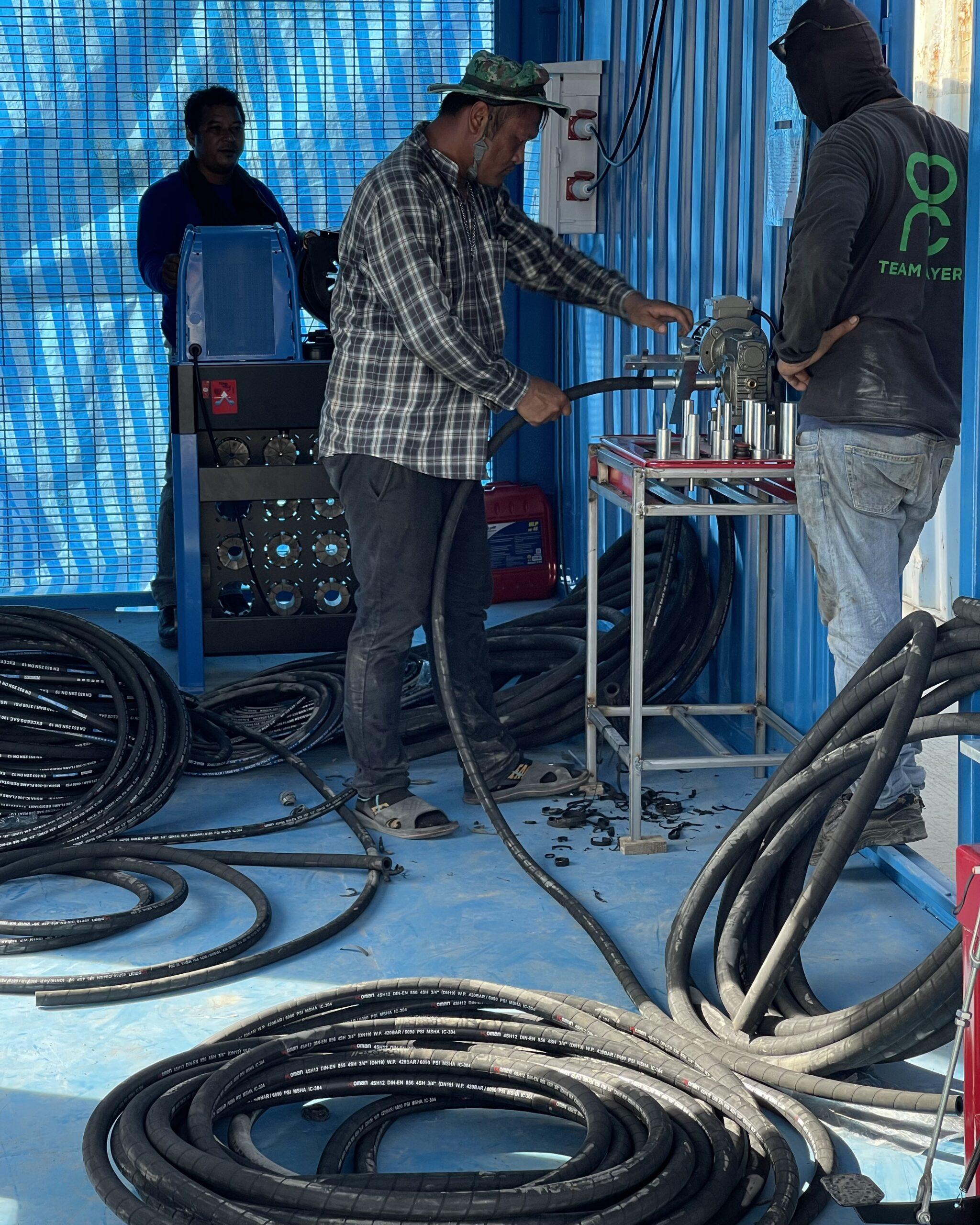
The installation of the Hydraulic hose assembly machines , HYD hose crimping machine , HYD hose skiving machine , HYD hose cutting machine at the Hose Assembly Workshop, in-house training for the theory training and practical training
Subject : Training on Hose Assembly Parts , Hose Workshop
** Production work, spare parts, hydraulic hose assembly Job. Recondition Work**
As you wish to give the company To train your staff (In-House training) on Hose Parts in order to increase their experience, expertise and confidence in offering Hose Parts to your customers.
The company is very pleased On the day that I will come to serve you as well as propose topics to train your employees The details are as follows :-
Training course “Hose Parts Training Course”
1) Theory of Hose Assembly Manufacturing Techniques
2) Hose Selection
3) Fitting Selection
4) Hose Assembly Procedures
5) Installation Procedures (Hose Installation Procedures)
6) Safety Issues
7) Setting up the hydraulic hose crimping machine.
8) Teach you how to use a hydraulic hose crimping machine.
9) The measurement of HYD hose Assembly Parts
etc.
The Training for HYD Hose Assembling at hose assembly workshop.
The training was as follows :-
Hydraulic Hose Assembling Training for 2 and 4 plies reinforcement with high pressure fittings. measurement
Training courses mentioned above It takes about 120 minutes and at the end of the lecture It will be allowed to ask questions. by the speakers of the company happy to answer questions and consult any problems with Hose Parts.
The Training for HYD Hose Assembling at hose assembly workshop.
The training was as follows :-
Hydraulic Hose Assembling Training for 2 and 4 plies reinforcement with high pressure fittings.
Preparation of Chart Board for inspection attached at the hose assembly workshop and repair center , chart board, hydraulic lines and fittings.
Phase 1 Hose Type
Phase 2 Cut Length/Interaxle Length
Phase 3 Out Side Skive
Phase 4 Inside Skive
Phase 5 Inside/Outside Skive Control
Phase 6 1st Fitting/2nd Fitting
Phase 7 Orientation
Phase 8 Crimping Diameter and Crimping Diameter Control
Phases 9 Manufacturing Date Marking
Phase 10 Proof Test (if requested)
Phase 11 Hose Flushing (if requested)
Phase 12 Capping (if requested)
SHEETS OF REFERENCE
MANUFACTURING AND CONTROL SHEET
INTERNAL ORDER
INTERAXLE LEGTH INERPRETATION
FITTING ORIENTATION
CRIMPING DIAMETER CHART
INSTRUCTIONS P32/FP110
HOSE FLUSHING – REGOLATION MACHINE CHART
PROOF TEST REPORT
1.0 GOAL
Hose Assembly Assurance Manual defines assembly process in order to garantee and assure that all operation of assembly productions are made following requirements requested by Customer Specifications e by Manuli Specifications. 2.0 APPLICATION FIELD
Work and control phases described in this Manual are applicable only to the activity of Hose Assembly production.
Each assembly phase is numbered with reference to Manufacturing and Control Sheet 3.0 ABBREVIATIONS
STOS : STORE SUPERVISOR
PROD : PRODUCTION
PRODS : PRODUCTIONE SUPERVISOR
QAS : QUALITY ASSURANCE SUPERVISOR
NC : NON CONFORM PRODUCT
MF/C : MANUFACTURING AND CONTROL SHEET 4.0 RESPONSABILITY PRODS
Issue MF/C with reference to internal order and give to production.
Operate swaging machine. At this operation, PRODS has to assure on every hose assembly that they are made following MF/C.
PROD
Has the responsibility to assembly and to control along the manufacturing process following what is written in SF/C.
QAS
Operate test pressure machine and report test result.
Issue NON CONFORM PRODUCT SHEET of NC
PHASE 1 HOSE TYPE
OPERATIONS
MACHINE
SHEET OF REFERENCE
Take from the storage the type of hose with the same code indicated on MF/C
Write the hose lot# on M/FC
Attention: to facilitate traceability of hose assembly, the type of hose used to manufacture a single lot of hose assembly must possibly be of the same lot
PHASE 2 CUT LENGTH / INTERAXLE LENGTH
OPERATIONS
MACHINE
SHEET OF REFERENCE
Cut length is indicated in MF/C. If it is not specified, operate as follow:
n consider interaxle length “L” of assembly indicated in MF/C;
n subtract from the measure of interaxle length “L” the sum of fittings length “x”, considering the measure from the abutting end of rubber hose to the fitting interaxle
n subtract to the result obtained the extension obtained during the crimping phase (5mm for braided hose and 8mm for spiralled hose)
L
x
Set the hose cut measure
steel ruler
Attention: cut must be perpendicular to the hose
cut section
YES
NO
Switch on the machine and wait until the number of cycles is stable.
cutting machine
Rule downward speed of blade (knife) depending on type of hose to be cut. A wrong regulation of downward speed can break the blade. For spiralled hose : minimum speed for all other types : normal speed.
cutting machine
Speed can be regulated with the handle on the left of cutting machine. Turning the handle anticlockwise speed increases and viceversa.
cutting machine
Front side
handle
Control cut rubber hose length and writ it on MF/C.
Steel ruler
PHASE 3 OUTSIDE SKIVE
OPERATION
MACHINE
SHEET OF REFERENCE
Take the pin guide of the same diameter of hose to be skived (see marking on the pin).
Set the pin as the skive length indicated on MF/C measuring with caliper the distance between the abutting of pin and the knife.
Skive machine
Set the phase inverter to wheel the mandrel to anticlockwise
Switch the skive machine with the foot -switcher
Insert the hose in the mandrel to skive.
Skive depth must unwrap rubber to void damage till metallic reinforce is visible.
Be careful not to leave rubber dross, shavings on the hose.
Attention: skive has to be done just on hose with metallic reinforce.
PHASE 4 INSIDE SKIVE
OPERATIONS
MACHINE
SHEET OF REFERENCE
Spiralled hose must be skived inside.
Take the guide pin of the same diameter of the hose to be skived (see marking on the pin).
Set the ghiera as the skive length indicated on MF/C measuring the distance between the ghiera abutting and the knife.
Skive machine
Set the phase inverter to wheel the mandrel to clockwise
Switch the skive machine with the foot -switcher
Insert the hose in the mandrel to skive.
Skive depth must unwrap rubber to void damage till metallic reinforce is visible.
Be careful not to leave rubber droll, shavings inside the hose.
PHASE 5 INSIDE/OUTSIDE SKIVE CONTROL
OPERATIONS
MACHINE
SHEET OF REFERENCE
Control the skive length with caliper as indicated in MF/C.
Caliper
Operator must also consult with skiving chart for the skive length in order to prevent too long/to short skive.
Skiving Chart
If skive is out of the range, put the assembly hose in a NC area, QAS to fill the Non Conformity product sheet.
Non Conformity Product Sheet
PHASES 6 1ST FITTING / 2ND FITTING
OPERATIONS
MACHINE
SHEET OF REFERENCE
Fittings are stored boxes identified with the product code which recorded in stock cards and/or computer.
Take fittings indicated on MF/C of the same box.
Put in the fittings to the hoses as indicated on MF/C.
PHASE 7 ORIENTATION
OPERATIONS
MACHINE
SHEET OF REFERENCE
Block fittings in the vice.
Vice
Turn manually the other fitting, following the chart enclosed, till the value indicated on MF/C is visible on goniometer
Goniometer
PHASES 8 MANUFACTURING DATE MARKING
OPERATIONS
MACHINE
SHEET OF REFERENCE
Use electric pen to mark
date-month-year on the ferrule of the assembly hose.
Example : 30/12/43
Electric Pen
PHASES 9 CRIMPING DIAMETER AND CRIMPING DIAMETER CONTROL
OPERATIONS
MACHINE
SHEET OF REFERENCE
The crimping diameter is indicated on MF/C.
Consult crimping diameter chart to choose the set of dies required for the crimping diameter requested.
P32/FP 110
Crimping Diameter Chart
Be sure the machine is turned off.
Put in the correct dies. Make sure that all dies are completely sit on the master dies.
Operator must also consult with the crimping diameter chart in order to prevent the out of range of crimping diameter.
Crimping Diameter Chart
Switch the machine on.
P32/FP 110
Instructions P32/FP110
Set the right crimping diameter with the diameter setting device.
“
Instructions P32/FP110
Push the press button to crimp the hose.
“
Instructions P32/FP110
Control the crimping diameter with caliper. Operator must measure the crimping diameter in every change of diameter setting
If crimping diameter is out of range, put the assembly hose in a NC area, QAS to fill the Non Conformity Product Sheet.
Non Conformity Product Sheet
PHASE 10 PROOF TEST (IF REQUESTED)
OPERATIONS
MACHINE
SHEET OF REFERENCE
Supply the bench with connections conform to hose to be tested.
Pressure bench
Customer Specifications
Switch on the bench and the computer.
Select or create the recipe. Remember that the proof pressure is double the working pressure written on the rubber hose.
Close the door and start the bench.
When cycle is finished write results on MF/C.
Print the report if requested by the Customer.
If there is leakage along the rubber or on the fittings, put the assembly hose in a NC area, QAS to fill the Non Conformity Product Sheet.
Non Conformity Product Sheet
PHASE 11 HOSE FLUSHING (IF REQUESTED)
OPERATIONS
MACHINE
SHEET OF REFERENCE
THE USE OF GLOVES IN THIS PHASE IS COMPULSORY
Control oil level with dipstick. If oil is under the half fill it up with oil.
Dipstick
Prepare the machine according to the hoses diameter, following the machine chart for the time and number of pumps
FMX 150
MOD. MOT06
Screw hoses on the rack in the correct way, being careful with long hoses, with wide bend radius (it is sufficient to screw two turns)
Push the two buttons on the sides of the bench. Door closes and automatically cycle works.
Front side
buttons
Door opens automatically, unscrew the hoses and put them on the rack to drip.
Attention: fluid used in this phase is oil for spark erosion (BP/HP-0 FINA IT/11-004 FINA PARAPUR/1013) and pollution grade to specifics NAS 1638 is checked monthly in an outside laboratory.
According to the analysis results: if the value of fluid is less or equal to 8 NAS can be used till the following month; if it is more or equal to 9 NAS must be changed by TEQ.
PHASE 12 CAPPING (IF REQUESTED)
OPERATIONS
MACHINE
SHEET OF REFERENCE
Take caps according to hose type and diameter.
Cap fittings when hoses are completely dry (if flushed).
NOTE The handling of hoses from the cutting phase to the fitting assembly/crimping one and from the latter and the flushing phase, has to be done by racks which can garantee outside hose cleanliness and prevent abrasions due to trailing along the floor.
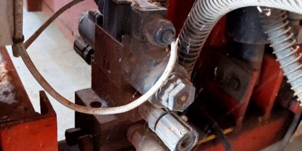
Hydraulic System of Corrugated Folding Machine Project : To build the new Corugated Folding machne W 2150 x L 4770 x H 3200 + HYD 250 bar power unit W 800 x L 1350 x H 1000 + Structure H-beam X-section 200 x 200
Phase 1 Hose Type
Phase 2 Cut Length/Interaxle Length
Phase 3 Out Side Skive
Phase 4 Inside Skive
Phase 5 Inside/Outside Skive Control
Phase 6 1st Fitting/2nd Fitting
Phase 7 Orientation
Phase 8 Crimping Diameter and Crimping Diameter Control
Phases 9 Manufacturing Date Marking
Phase 10 Proof Test (if requested)
Phase 11 Hose Flushing (if requested)
Phase 12 Capping (if requested)
SHEETS OF REFERENCE
MANUFACTURING AND CONTROL SHEET
INTERNAL ORDER
INTERAXLE LEGTH INERPRETATION
FITTING ORIENTATION
CRIMPING DIAMETER CHART
INSTRUCTIONS P32/FP110
HOSE FLUSHING – REGOLATION MACHINE CHART
PROOF TEST REPORT
1.0 GOAL
Hose Assembly Assurance Manual defines assembly process in order to garantee and assure that all operation of assembly productions are made following requirements requested by Customer Specifications e by Manuli Specifications. 2.0 APPLICATION FIELD
Work and control phases described in this Manual are applicable only to the activity of Hose Assembly production.
Each assembly phase is numbered with reference to Manufacturing and Control Sheet 3.0 ABBREVIATIONS
STOS : STORE SUPERVISOR
PROD : PRODUCTION
PRODS : PRODUCTIONE SUPERVISOR
QAS : QUALITY ASSURANCE SUPERVISOR
NC : NON CONFORM PRODUCT
MF/C : MANUFACTURING AND CONTROL SHEET 4.0 RESPONSABILITY PRODS
Issue MF/C with reference to internal order and give to production.
Operate swaging machine. At this operation, PRODS has to assure on every hose assembly that they are made following MF/C.
PROD
Has the responsibility to assembly and to control along the manufacturing process following what is written in SF/C.
QAS
Operate test pressure machine and report test result.
Issue NON CONFORM PRODUCT SHEET of NC
PHASE 1 HOSE TYPE
OPERATIONS
MACHINE
SHEET OF REFERENCE
Take from the storage the type of hose with the same code indicated on MF/C
Write the hose lot# on M/FC
Attention: to facilitate traceability of hose assembly, the type of hose used to manufacture a single lot of hose assembly must possibly be of the same lot
PHASE 2 CUT LENGTH / INTERAXLE LENGTH
OPERATIONS
MACHINE
SHEET OF REFERENCE
Cut length is indicated in MF/C. If it is not specified, operate as follow:
n consider interaxle length “L” of assembly indicated in MF/C;
n subtract from the measure of interaxle length “L” the sum of fittings length “x”, considering the measure from the abutting end of rubber hose to the fitting interaxle
n subtract to the result obtained the extension obtained during the crimping phase (5mm for braided hose and 8mm for spiralled hose)
L
x
Set the hose cut measure
steel ruler
Attention: cut must be perpendicular to the hose
cut section
YES
NO
Switch on the machine and wait until the number of cycles is stable.
cutting machine
Rule downward speed of blade (knife) depending on type of hose to be cut. A wrong regulation of downward speed can break the blade. For spiralled hose : minimum speed for all other types : normal speed.
cutting machine
Speed can be regulated with the handle on the left of cutting machine. Turning the handle anticlockwise speed increases and viceversa.
cutting machine
Front side
handle
Control cut rubber hose length and writ it on MF/C.
Steel ruler
PHASE 3 OUTSIDE SKIVE
OPERATION
MACHINE
SHEET OF REFERENCE
Take the pin guide of the same diameter of hose to be skived (see marking on the pin).
Set the pin as the skive length indicated on MF/C measuring with caliper the distance between the abutting of pin and the knife.
Skive machine
Set the phase inverter to wheel the mandrel to anticlockwise
Switch the skive machine with the foot -switcher
Insert the hose in the mandrel to skive.
Skive depth must unwrap rubber to void damage till metallic reinforce is visible.
Be careful not to leave rubber dross, shavings on the hose.
Attention: skive has to be done just on hose with metallic reinforce.
PHASE 4 INSIDE SKIVE
OPERATIONS
MACHINE
SHEET OF REFERENCE
Spiralled hose must be skived inside.
Take the guide pin of the same diameter of the hose to be skived (see marking on the pin).
Set the ghiera as the skive length indicated on MF/C measuring the distance between the ghiera abutting and the knife.
Skive machine
Set the phase inverter to wheel the mandrel to clockwise
Switch the skive machine with the foot -switcher
Insert the hose in the mandrel to skive.
Skive depth must unwrap rubber to void damage till metallic reinforce is visible.
Be careful not to leave rubber droll, shavings inside the hose.
PHASE 5 INSIDE/OUTSIDE SKIVE CONTROL
OPERATIONS
MACHINE
SHEET OF REFERENCE
Control the skive length with caliper as indicated in MF/C.
Caliper
Operator must also consult with skiving chart for the skive length in order to prevent too long/to short skive.
Skiving Chart
If skive is out of the range, put the assembly hose in a NC area, QAS to fill the Non Conformity product sheet.
Non Conformity Product Sheet
PHASES 6 1ST FITTING / 2ND FITTING
OPERATIONS
MACHINE
SHEET OF REFERENCE
Fittings are stored boxes identified with the product code which recorded in stock cards and/or computer.
Take fittings indicated on MF/C of the same box.
Put in the fittings to the hoses as indicated on MF/C.
PHASE 7 ORIENTATION
OPERATIONS
MACHINE
SHEET OF REFERENCE
Block fittings in the vice.
Vice
Turn manually the other fitting, following the chart enclosed, till the value indicated on MF/C is visible on goniometer
Goniometer
PHASES 8 MANUFACTURING DATE MARKING
OPERATIONS
MACHINE
SHEET OF REFERENCE
Use electric pen to mark
date-month-year on the ferrule of the assembly hose.
Example : 30/12/43
Electric Pen
PHASES 9 CRIMPING DIAMETER AND CRIMPING DIAMETER CONTROL
OPERATIONS
MACHINE
SHEET OF REFERENCE
The crimping diameter is indicated on MF/C.
Consult crimping diameter chart to choose the set of dies required for the crimping diameter requested.
P32/FP 110
Crimping Diameter Chart
Be sure the machine is turned off.
Put in the correct dies. Make sure that all dies are completely sit on the master dies.
Operator must also consult with the crimping diameter chart in order to prevent the out of range of crimping diameter.
Crimping Diameter Chart
Switch the machine on.
P32/FP 110
Instructions P32/FP110
Set the right crimping diameter with the diameter setting device.
“
Instructions P32/FP110
Push the press button to crimp the hose.
“
Instructions P32/FP110
Control the crimping diameter with caliper. Operator must measure the crimping diameter in every change of diameter setting
If crimping diameter is out of range, put the assembly hose in a NC area, QAS to fill the Non Conformity Product Sheet.
Non Conformity Product Sheet
PHASE 10 PROOF TEST (IF REQUESTED)
OPERATIONS
MACHINE
SHEET OF REFERENCE
Supply the bench with connections conform to hose to be tested.
Pressure bench
Customer Specifications
Switch on the bench and the computer.
Select or create the recipe. Remember that the proof pressure is double the working pressure written on the rubber hose.
Close the door and start the bench.
When cycle is finished write results on MF/C.
Print the report if requested by the Customer.
If there is leakage along the rubber or on the fittings, put the assembly hose in a NC area, QAS to fill the Non Conformity Product Sheet.
Non Conformity Product Sheet
PHASE 11 HOSE FLUSHING (IF REQUESTED)
OPERATIONS
MACHINE
SHEET OF REFERENCE
THE USE OF GLOVES IN THIS PHASE IS COMPULSORY
Control oil level with dipstick. If oil is under the half fill it up with oil.
Dipstick
Prepare the machine according to the hoses diameter, following the machine chart for the time and number of pumps
FMX 150
MOD. MOT06
Screw hoses on the rack in the correct way, being careful with long hoses, with wide bend radius (it is sufficient to screw two turns)
Push the two buttons on the sides of the bench. Door closes and automatically cycle works.
Front side
buttons
Door opens automatically, unscrew the hoses and put them on the rack to drip.
Attention: fluid used in this phase is oil for spark erosion (BP/HP-0 FINA IT/11-004 FINA PARAPUR/1013) and pollution grade to specifics NAS 1638 is checked monthly in an outside laboratory.
According to the analysis results: if the value of fluid is less or equal to 8 NAS can be used till the following month; if it is more or equal to 9 NAS must be changed by TEQ.
PHASE 12 CAPPING (IF REQUESTED)
OPERATIONS
MACHINE
SHEET OF REFERENCE
Take caps according to hose type and diameter.
Cap fittings when hoses are completely dry (if flushed).
NOTE The handling of hoses from the cutting phase to the fitting assembly/crimping one and from the latter and the flushing phase, has to be done by racks which can garantee outside hose cleanliness and prevent abrasions due to trailing along the floor.