A hydraulic system contains and confines a liquid in such a way that it uses the laws governing liquids to transmit power and do work. This chapter describes some basic systems and discusses components of a hydraulic system that store and condition the fluid. The oil reservoir (sump or tank) usually serves as a storehouse and a fluid conditioner. Filters, strainers, and magnetic plugs condition the fluid by removing harmful impurities that could clog passages and damage parts. Heat exchanges or coolers often are used to keep the oil temperature within safe limits and prevent deterioration of the oil. Accumulators, though technically sources of stored energy, act as fluid storehouses. 2-1. Basic Systems. The advantages of hydraulic systems over other methods of power transmission are—
• Simpler design. In most cases, a few pre-engineered components will replace complicated
mechanical linkages.
• Flexibility. Hydraulic components can be located with considerable flexibility. Pipes
and hoses in place of mechanical elements virtually eliminate location problems.
• Smoothness. Hydraulic systems are smooth and quiet in operation. Vibration is kept
to a minimum.
• Control. Control of a wide range of speed and forces is easily possible.
• Cost. High efficiency with minimum friction loss keeps the cost of a power transmission
at a minimum.
• Overload protection. Automatic valves guard the system against a breakdown from
overloading.
The main disadvantage of a hydraulic system is maintaining the precision parts when they are exposed to bad climates and dirty atmospheres. Protection against rust, corrosion, dirt, oil deterioration, and other adverse environment is very important. The following paragraphs discuss several basic hydraulic systems. a. Hydraulic Jack.In this system (Figure 2-1, page 2-2), a reservoir and a system of valves has been added to Pascal’s hydraulic lever to stroke a small cylinder or pump continuously and raise a large piston or an actuator a notch with each stroke. Diagram A shows an intake stroke. An outlet check valve closes by pressure under a load, and an inlet check valve opens so that liquid from the reservoir fills the pumping chamber. Diagram B shows the pump stroking downward. An inlet check valve closes by pressure and an outlet valve opens. More liquid is pumped under a large piston to raise it. To lower a load, a third valve (needle valve) opens, which opens an area under a large piston to the reservoir. The load then pushes the piston down and forces the liquid into the reservoir. b. Motor-Reversing System. Figure 2-2, page 2-3, shows a power-driven pump operating a reversible rotary motor. A reversing valve directs fluid to either side of the motor and back to the reservoir. A relief valve protects the system against excess pressure and can bypass pump output to the reservoir, if pressure rises too high. c. Open-Center System.In this system, a control-valve spool must be open in the center to allow pump flow to pass through the valve and return to the reservoir. Figure 2-3, page 2-4, shows this system in the neutral position. To operate several functions simultaneously, an open-center system must have the correct connections, which are discussed below. An open-center system is efficient on single functions but is limited with multiple functions. (1) Series Connection. Figure 2-4, page 2-4, shows an open-center system with a series connection. Oil from a pump is routed to the three control valves in series. The return from the first valve is routed to the inlet of the second, and so on. In neutral, the oil passes through the valves in series and returns to the reservoir, as the arrows indicate. When a control valve is operated, the incoming oil is diverted to the cylinder that the valve serves. Return liquid from the cylinder is directed through the return line and on to the next valve.
This system is satisfactory as long as only one valve is operating at a time. When this happens, the full output of the pump at full system pressure is available to that function. However, if more than one valve is operating, the total of the pressures required for each function cannot exceed the system’s relief setting.
Figure 2-1. Hydraulic jack
Figure 2-2. Motor-reversing system
Figure 2-3. Open-center system
Figure 2-4. Open-center system with a series connection
(2) Series/Parallel Connection. Figure 2-5 shows a variation on the series-connected type. Oil from the pump is routed through the control valves in series, as well as in parallel. The valves are sometimes stacked to allow for extra passages. In neutral, a liquid passes through the valves in series, as the arrows indicate. However, when any valve is operating, the return is closed and the oil is available to all the valves through the parallel connection.
When two or more valves are operated at once, the cylinder that needs the least pressure will operate first, then the cylinder with the next least, and so on. This ability to operate two or more valves simultaneously is an advantage over the series connection. (3) Flow Divider. Figure 2-6, page 2-6, shows an open-center system with a flow divider. A flow divider takes the volume of oil from a pump and divides it between two functions. For example, a flow divider might be designed to open the left side first in case both control valves were actuated simultaneously. Or, it might divide the oil to both sides, equally or by percentage. With this system, a pump must be large enough to operate all the functions simultaneously. It must also supply all the liquid at the maximum pressure of the highest function, meaning large amounts of HP are wasted when operating only one control valve. d. Closed-Center System. In this system, a pump can rest when the oil is not required to operate a function. This means that a control valve is closed in the center, stopping the flow of the oil from the pump. Figure 2-7, page 2-6, shows a closed-center system. To operate several functions simultaneously, a closed-center system have the following connections: (1) Fixed-Displacement Pump and Accumulator. Figure 2-8, page 2-7, shows a closed center system. In this system, a pump of small but constant volume charges an accumulator.
Figure 2-5. Open-center system with a series/parallel connection
Figure 2-6. Open-center system with a flow divider
Figure 2-7. Closed-center system
Figure 2-8. Fixed-displacement pump and accumulator
When an accumulator is charged to full pressure, an unloading valve diverts the pump flow back to a reservoir. A check valve traps the pressured oil in the circuit.
When a control valve is operated, an accumulator discharges its oil and actuates a cylinder. As pressure begins to drop, an unloading valve directs the pump flow to an accumulator to recharge the flow. This system, using a small capacity pump, is effective when operating oil is needed only for a short time. However, when the functions need a lot of oil for longer periods, an accumulator system cannot handle it unless the accumulator is very large. (2) Variable-Displacement Pump. Figure 2-9, page 2-8, shows a closed-center system with a variable-displacement pump in the neutral mode. When in neutral, oil is pumped until the pressure rises to a predetermined level. A pressure-regulating valve allows the pump to shut off by itself and maintain this pressure to the valve. When the control valve is operating, oil is diverted from the pump to the bottom of a cylinder. The drop in pressure caused by connecting the pump’s pressure line to the bottom of the cylinder causes the pump to go back to work, pumping oil to the bottom of the piston and raising the load.
When the valve moves, the top of the piston connects to a return line, which allows the return oil that was forced from the piston to return to the reservoir or pump. When the valve returns to neutral, oil is trapped on both sides of the cylinder, and the pressure passage from the pump is dead-ended. After this sequence, the pump rests. Moving the spool in the downward position directs oil to the top of the piston, moving the load downward. The oil from the bottom of the piston is sent into the return line.
Figure 2-10, page 2-8, shows this closed-center system with a charging pump, which pumps oil from the reservoir to the variable-displacement pump. The charging pump supplies only the makeup oil required in a system and provides some inlet pressure to make a variabledisplacement pump more efficient. The return oil from a system’s functions is sent directly to the inlet of a variable-displacement pump.
Figure 2-9. Variable-displacement pump
Figure 2-10. Closed-center system with charging pump
Because today’s machines need more hydraulic power, a closed-center system is more advantageous. For example, on a tractor, oil may be required for power steering, power brakes, remote cylinders, three-point hitches, loaders, and other mounted equipment. In most cases, each function requires a different quantity of oil. With a closed-center system, the quantity of oil to each function can be controlled by line or valve size or by orificing with less heat build up when compared to the flow dividers necessary in a comparable open-center system. Other advantages of a closed-center system are as follows:
It does not require relief valves because the pump simply shuts off by itself when standby pressure is reached. The prevents heat buildup in systems where relief pressure is frequently reached.
The size of the lines, valves, and cylinders can be tailored to the flow requirements of each function.
Reserve flow is available, by using a larger pump, to ensure full hydraulic speed at low engine revolutions per minute (rpm). More functions can be served.
It is more efficient on functions such as brakes, which require force but very little piston movement. By holding the valve open, standby pressure is constantly applied to the brake piston with no efficiency loss because the pump has returned to standby.
Hydraulics Training Manual
BASIC HYDRAULICS AND HYDRAULIC PLUMBING
Synthetic rubber hoses
TYPES OF HOSE
Aircraft hose is composed of two or more layers of differing materials. The inner layer, or liner, is a leak-tight nonmetallic tube made from either synthetic rubber or teflon. The liner is reinforced against swelling or bursting by one or more outer layers of braid that encircle it. The kind and number of layers of braid depend on the intended operating pressure range of the hose assembly.
The two materials used as inner liner for flexible hoses are synthetic rubber and teflon. The two materials and their uses are discussed in the paragraphs that follow. Rubber Hose.
The inner liner of rubber hose used in aircraft plumbing systems is made of synthetic rubber. Various compounds of rubber are used for these inner liners. Each compound provides the hose with some special capability, such as usability with certain fluids or operability within certain ranges of temperature. The outer covering of rubber hose is made of either fabric or rubber.
Rubber hose is used in aircraft plumbing systems only in the form of assemblies. An assembly is formed by attaching metal end connections to each end of a section of bulk hose. Teflon Hose.
Teflon is the registered name for tetrafluoroethylene, which is a synthetic resin. Teflon hose has a flexible leak-proof inner tube, reinforced on the outside with one or more layers of stainless steel braid. The teflon linear is chemical inert to all fuel, oil, alcohol, water, acid, and gas. The linear can withstand fluid temperatures ranging from -100 F to + 500 F (-73 C to +260 C). Like rubber hose, teflon hose is used in aircraft plumbing systems only as assemblies.
Marking on Rubber Hose.
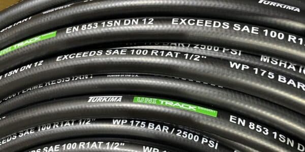
Bulk rubber hose has ink or paint markings on its outer cover for identification. The information provided by these markings include the identity of the manufacturer, date made, size, and military specification number. The military specification (MS) number provides additional information when referenced with a specification table of TM 1-1500-204-23-2. This information includes the hose-pressure capability, temperature limitations, and the fluids that can be used. On some hose, a lay strip provides an easy method to determine if an installed hose is twisted.
To identify field-fabricated rubber hose assemblies, a metal band is placed around the hose to identify the federal or national stock number of the assembly and to give the operating pressure and pressure test date.
Medium pressure rubber hose assemblies are fabricated from bulk hose conforming to military specification MIL-H-8794 and fittings conforming to military standard MS 28740. Prior to the assembly process and before cutting, visually check the bulk hose for any mutilations, marks, seams, and excessive graphite. Check the fittings for mutilations to the threaded areas, nicks, distortions, scratches, or any other damage to the cone seat sealing surface, or to the finish that can affect the corrosion resistance of the fitting.
After the hose and fittings have been inspected, determine the correct length of hose required as shown in Figure 2-15. Cut the hose squarely, using a fine tooth hacksaw; then, using compressed air, clean the hose to remove all cutting residue.
Fabricating High-Pressure Teflon Hose Assemblies.
High-pressure teflon hose assemblies are manufactured from bulk hose conforming to MIL-H-83298 and end fittings conforming to MIL-H-83296.
Figure 2-16. Assembly of Hose and End Fitting.
INSTALLING HOSE ASSEMBLIES
During operation, the hose assemblies changes in length from +2 percent to -4 percent because of pressurization. To compensate for this, slack equal to at least five percent of the hose length must be allowed for expansion and shrinkage. The five percent allowance must be provided during cutting and fabricating. In addition to hose length, care must be taken not to twist the hose or to exceed the allowed bend radius. Supports and grommets must be used, fittings lubricated, and protection against temperature provided. Each of these is discussed in the paragraphs that follow and illustrated in
Figure 2-17. Twisting.
Most hose is marked with a lengthwise solid line (lay strip) for ease in detecting any twists of the line during installation. A twisted hose tends to untwist when pressurized causing the end fitting to become loosened or sheared. To avoid twisting hose assemblies when connecting the second end, use two wrenches: one to hold the stationary fitting and one to turn the swivel nut. Bend Radius.
Hose, like rigid tubing, has a limit to its bend allowance. Bends exceeding the permissible limit lead to early failure of the hose assembly. The radius of the sharpest bend permissible for a hose is referred to as the minimum bend radius for that hose. This bend radius is measured in the same manner as the
minimum bend radius of rigid tubing as described in the paragraph of this lesson entitled “routing of lines”. Supports and Grommets.
Teflon hose requires a different kind of support than that used for rubber hose. However, the following principles in using supports apply to both rubber and teflon hose.
Hose must be supported along its length at intervals of 24 inches or less, depending on the size of the hose. These supports, shown in Figure 2-18, must be installed in such a manner that they do not cause deflection of any rigid lines where they are connected.
When a hose is connected to an engine by a hose clamp, a support must be placed approximately three inches from the connection, and at least 1-1/2 inches of hose slack provided between the connection and the engine, to keep vibration and torsion from damaging the connections.
When a hose passes through a bulkhead, a grommet must be installed in the bulkhead hole to provide support for the hose and to prevent it from chafing. As an alternative, a cushioned clamp can be used at the hole if the hole is large enough to provide adequate clearance around the hose.
A hose assembly connecting two rigidly mounted fittings must be supported firmly but not rigidly. Lubrication.
The swiveling parts and mating surfaces-of hose assemblies must be lubricated before installation. This ensures effective seating and tightening of the component parts. Oil or water can be used on all, types of fuel, oil, and coolant hose when installation is made except for self-sealing hose which must never be lubricated during installation. However, only oil or the operational fluid of the system must be used on hydraulic and pneumatic hose.
Figure 2-17. Connecting Hose Assemblies.
Figure 2-18. Hose Support.
Temperature Protection.
Hose must be protected from high temperatures such as exhaust blast and hot engine parts. In these areas the hose must either be shielded or relocated. A shield for temperature protection is shown in Figure 2-19.
Figure 2-19. Temperature Protection.
STORAGE
Proper storage and handling of aircraft hose and hose assemblies are the responsibility of all activities engaged in aircraft maintenance. Aircraft hose and associated rubber components must be stored in a dark, cool, dry place protected from exposure to strong air currents and dirt. Stored rubber hose and seals must also be protected from electric motors or other equipment emitting heat or ozone. Hose and hose components must be stored in the original packing and issued so that the oldest items are issued first. Neither teflon nor rubber hose has limited shelf life. However, prior to installation all hose assemblies must be inspected to ensure serviceability and tested according to the procedures listed in the paragraph on testing hose assemblies. Bulk Hose.
Prior to being placed in storage, the ends of the hose must be capped to prevent flareout and dirt contamination. Storage in a straight position is the preferred manner; however, if coiling is necessary, large loose coils must be made.
Hose Assemblies. The ends of all hose assemblies must be capped during storage with polyethylene protective plugs conforming toNational Aerospace Standard (NAS) 815 or equivalent to prevent contamination.
Flexible hoses .
(1) Rubber Hose.
Rubber hose is a flexible hose that consists of a seamless, synthetic rubber tube covered with layers of cotton braid and wire braid. Figure 2-22, page 2-20, shows cut-away views of typical rubber hose. An inner tube is designed to withstand material passing through it. A braid, which may consist of several layers, is the determining factor in the strength of a hose. A cover is designed to withstand external abuse.
When installing flexible hose, do not twist it. Doing so reduces its lift and may cause its fittings to loosen. An identification stripe that runs along the hose length should not spiral, which would indicate twisting (Figure 2-23).
Protect flexible hose from chafing by wrapping it lightly with tape, when necessary.
The minimum bend radius for flexible hose varies according to its size and construction
and the pressure under which a system will operate. Consult the applicable publications that contain the tables and graphs which show the minimum bend radii for the different types of installations. Bends that are too sharp will reduce the bursting pressure of flexible hose considerably below its rated value.
Do not install flexible hose so that it will be subjected to a minimum of flexing during operation. Never stretch hose tightly between two fittings. When under pressure, flexible hose contracts in length and expands in diameter.
Figure 2-22. Flexible rubber hose
(2) Teflon™-Type Hose.
This is a flexible hose that is designed to meet the requirements of higher operating pressures and temperatures in today’s fluid-powered systems. The hose consists of a chemical resin that is processed and pulled into a desired-size tube shape. It is covered with stainless-steel wire that is braided over the tube for strength and protection. Teflon-type hose will not absorb moisture and is unaffected by all fluids used in today’s fluid-powered systems. It is nonflammable; however, use an asbestos fire sleeve where the possibility of an open flame exists.
Figure 2-23. Installing flexible hose
Carefully handle all Teflon-type hose during removal or installation. Sharp or excessive bending will kink or damage the hose. Also, the flexible-type hose tends to form itself to the installed position in a circulatory system.