ข้อต่อ Adapters : ข้อต่อ # JM-BMT : ข้อต่อตรง Straight Adapter fitting JIC Male x BSPT Male ( JT-SP ) ( JM-PM ) ( JM-BMT )


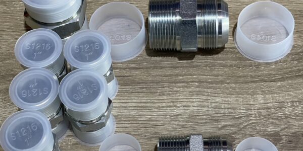
ข้อต่อ Adapters : ข้อต่อ # JM-BMT : ข้อต่อตรง Straight Adapter fitting JIC Male x BSPT Male ( JT-SP ) ( JM-PM ) ( JM-BMT )
ข้อต่ออะแด็ปเตอร์ ไฮดรอลิค Hydraulic Adapter Fittings
รายการ ข้อต่อ อะแด็ปเตอร์ นอก ( ต่างประเทศ )


 CAT adapter HMC รายการ ข้อต่อ อะแด็ปเตอร์ จีน
วิธีการระบุพอร์ตและตัวเชื่อมต่อของไหล
วัดเส้นผ่านศูนย์กลางเกลียวด้วย Id / OD Caliper ใช้เกจวัดระยะเกลียวเพื่อกำหนดจำนวนเกลียวต่อนิ้วหรือระยะห่างระหว่างเกลียวในการเชื่อมต่อแบบเมตริก
แยกแยะ พอร์ตของไหล และ ตัวเชื่อมต่อ ยังไง แนะนำ ถึง ระบบเกลียว อเมริกัน, อังกฤษ, ญี่ปุ่น, เยอรมัน (DIN เมตริก) และ ISO การเชื่อมต่อ
How to Identify Fluid Ports and Connectors.
A guide to North American, British, Japanese, German (DIN metric), and ISO connections

How to measure threads
Measure the thread diameter with an I.D./O.D. caliper. When comparing your measurements with the dimensions shown in this guide, remember threads can become worn and distorted from use. Your measurements may not match exactly to the figures shown in our tables.

Use a thread pitch gauge to determine the number of threads per inch or the distance between threads in metric connections. Place the gauge on the threads until the fit is snug. Match your measurements with the tables in this guide.

How to measure four-bolt flanges
First measure the port hole diameter using a caliper. Next, measure the longest bolt hole spacing from center to center or measure the flange head diameter.Dash numbersMost fluid pipe and tube sizes in the United States are identified by dash numbers, abbreviations that make ordering components easier.
Dash numbers are commonly expressed as the numerator of a fraction where the denominator is always 16. For example, a -04 port or connector is 4/16 or 1/4 inch. Dash numbers are usually nominal (in name only).Metric threads are actual size and do not use dash numbers. For example, M16x1.5 = 16 mm thread O.D. with 1.5 mm between each thread i
Amercial Dryseal Pipe Threads
National Pipe Tapered Fuel (NPTF)
This connection is still widely used in fluid power systems, even though it is not recommended by the National Fluid Power Association (NFPA) for use in hydraulic applications. The thread is tapered and the seal takes place by deformation of the threads.
NPTF Thread Tip: Measure the thread diameter and subtract one quarter inch to find the nominal pipe size.
 NPTF thread
National Pipe Straight Mechanical (NPSM)
This connection is sometimes used in fluid power systems. The female half has a straight thread and an inverted 30° seat. The male half has a straight thread and a 30° internal chamfer. The 30° seat of the female seals against the chamfer on the male. The threads hold the connection mechanically.A properly chamfered NPTF male (page 2) will also seal with a NPSM female.
 NPSM thread
JIC 37° Flare
SAE J514
Originally named for the now-defunt Joint Industrial Commission (JIC), this connection is very common in fluid power systems. Both the male and female halves of this connection have 37° seats. The seal takes place by establishing a line of contact between the male flare and the female cone seat. The threads hold the connection mechanically. This connection is also commonly used with flared tubing (not pictured)
 JIC thread
SAE 45° Flare
SAE J512
This connection is very common in refrigeration, automotive and truck piping systems. The connectors are frequently made of brass. Both the male and female halves of this connection have 45° seats. The seal takes place between the male flare and the female cone seat. The threads hold the connection mechanically.
This connection is also commonly used with flared tubing (not pictured).
 SAE 45 degree Flare
SAE Straight Thread O-Ring (ORB)
SAE J1926-1 and ISO 11296-1
Caution: In sizes – 02, – 03, – 04, 05, – 08 and – 10, the threads of the SAE 37° flare and SAE 45° flare are the same. However, the sealing surface angles are not the same.
Conforms to MS16142, UN/UNF Threads
This port connection (sometimes called O-Ring Boss) is recommended for optimum leakage control in medium and high pressure hydraulic systems. The male connector has a straight thread and an O-ring. The female port has a straight thread, a machined surface (minimal spotface) and a chamfer to accept the O-ring. The seal takes place by compressing the O-ring into the chamfer. The threads hold the connection mechanically.
 ORB thread
Flareless Compression.
SAE J514
The male connector has parallel threads and a 24° seat. The female half of this connection incorporates a bite-type ferrule/sleeve used in conjunction with a tube and a female nut. When the nut is tightened, the seal is made between the sleeve and the 24° seat. A seal is also made between the sleeve and the tubing. The threads hold the connection mechanically
 Flare less Compression thread
O-Ring Face Seal (ORFS)
SAE J1453
This connection offers the very best leakage control available today. The male connector has a straight thread and O-ring in the face. The female has a straight thread and a machined flat face. The seal takes place by compressing the O-ring onto the flat face of the female, similar to a flange type fitting. The threads hold the connection mechanically.
 ORFS thread
Inverted Flare
SAE J512
This connection is frequently used in automotive systems. The male connector can either be a 45° flare in the tube fitting form or a 42° seat in the machined adapter form. The female has a straight thread with a 42° inverted flare. The seal takes place on the flared surfaces. The threads hold the connection mechanically.
 Inverted Flare thread
Four-Bolt Flange
SAE J518 and ISO 6162
Interchangeable with DIN 20066 and JIS B 8363, except for the bolt sizes.
This connection is commonly used worldwide to connect larger size hose and tubing (1/2″ to 3″) in fluid power systems. An O-ring, inserted into a ring groove in the flange head, seals on a smooth faced female port, and is held in place by two clamp halves and four bolts in rectangular pattern.
ISO 6162 / SAE J518 flanges come in two pressure classes: the standard series Code 61 and the high pressure (6,000 psi) Code 62.
 Four-Bolt Flanges
Note: CAT thick flanges have a flange thickness of 0.56″ (all sizes) to interchange with Caterpillar® split flanges. All other CAT flange dimensions are identical to Code 62.
O-Ring Pilot Threads
This connection, sometimes known as Beadlock, is common to air condition- ing systems, both in vehicle and commercial applications. Both the male and female halves of the connection have a pilot, either long or short. The seal takes place by compressing an O-ring adjacent to the bead of the tube. The threads hold the connection mechanically.
 O-Ring Pilot Threads
British Standard Pipe
British Standard Pipe Parallel (BSPP)
The BSPP (parallel) male connection is similar to, but not interchangeable with, the American NPSM male. The thread pitches are different in most sizes. The female swivel BSPP has a tapered nose, which seals on the cone seat of the male.
 BSPP thread
British Standard Pipe threads are somtimes identified as “G” (for parallel threads) or “R” (for tapered threads) followed by a fractional dimension.
Example: 1⁄2– 14 BSPP may be expressed as G 1⁄2
British Standard Pipe Tapered (BSPT)
The BSPT (tapered) male connector is similar to American NPTF, but the thread pitches are different in most sizes. The thread form and diameters are close, but not identical. Sealing is accomplished by distorting the threads. A properly chamfered BSPT male will also seal with a BSPP female swivel.
 BSPT thread
Flat Face Port with BSPP Threads
ISO 1179-1
DIN 3852, Part 2
Parallel threads seal using various sealing rings or washers, such as O-rings, bonded seals or metal to metal seals. The female port has a machined flat surface (spotface) which the male seals against.
Please see the ISO 228-1 “G” or BSPP thread dimensions.
 BSPP Flat Face
Flat Face Port with Metric Threads
ISO 9974-1
DIN 3852, Part 1
This connecion is similar to ISO 1179-1, except for the metric threads. The fittings have parallel threads and seal using various sealing rings, washers or metal to metal seals.
For illustration, please see the diagrams of ISO 1179-1 on the facing page.
ISO 261 “M” Metric Threads
 Metric Thread Flat Face
 Metric Flat Face
Metric Port and Stud Ends
ISO 6149
ISO 261 Metric Threads and O-Ring Seal
This port connection is similar to the SAE J1926-1 Straight Thread O-Ring , except for the metric threads. The male connector has a straight metric thread and an O-ring. The female port has a straight metric thread, a machined surface(minimum spotface) and a chamfer to accept the O-ring. The seal is created by compressing the O-ring into the chamfer, and the threads hold the connection mechanically.

M14x1.5 is recommended for diagnostic port applications.
Metric 60° Cone
DIN 7631
This thread is frequently used in hydraulic systems. The male connector has a straight metric thread and a 60° (included angle) recessed cone. The female has a straight thread and a tapered nose/globeseal seat. The seal takes place between the cone of the male and nose of the tapered nose/globeseal flareless swivel. The threads hold the connection mechanically.
 60 degree cone seat
Metric Tube Compression / 24° Cone.
DIN 2353
This metric system consists of one male and three female connectors, all of which have straight metric threads. Sealing takes place between the 24° seat in the male connector and the respective sealing areas in the female connectors.
 Metric Tube Compression / 24° Cone
DIN 2353 L and DIN 2353 S
Metric tube compression fittings include two connections, the DIN 2353 L “light” series and the DIN 2353 S “heavy” series. The thread dimensions and tube sizes are different for each series.
 Metric tube compression
Japanese Industrial Standard
JIS 30° Flare
The JIS 30° flare connection is similar to the American JIC 37° flare (page 4), except for the 30° seat angle and the JIS B 0202 thread dimensions, which are the same as BSPP.
 JIS 30 degree flare
Komatsu 30° Flare
JIS Metric
Used extensively on Komatsu equipment, this connection has a 30° seat and parallel metric threads. Also referred to as JIS Metric, Komatsu fittings are sometimes confused with JIS 30° flare which has BSPP thread dimensions.

วิธีการระบุพอร์ตและตัวเชื่อมต่อของไหล
วัดเส้นผ่านศูนย์กลางเกลียวด้วย Id / OD Caliper ใช้เกจวัดระยะเกลียวเพื่อกำหนดจำนวนเกลียวต่อนิ้วหรือระยะห่างระหว่างเกลียวในการเชื่อมต่อแบบเมตริก
แยกแยะ พอร์ตของไหล และ ตัวเชื่อมต่อ ยังไง แนะนำ ถึง ระบบเกลียว อเมริกัน, อังกฤษ, ญี่ปุ่น, เยอรมัน (DIN เมตริก) และ ISO การเชื่อมต่อ
How to Identify Fluid Ports and Connectors.
A guide to North American, British, Japanese, German (DIN metric), and ISO connections

How to measure threads
Measure the thread diameter with an I.D./O.D. caliper. When comparing your measurements with the dimensions shown in this guide, remember threads can become worn and distorted from use. Your measurements may not match exactly to the figures shown in our tables.

Use a thread pitch gauge to determine the number of threads per inch or the distance between threads in metric connections. Place the gauge on the threads until the fit is snug. Match your measurements with the tables in this guide.

How to measure four-bolt flanges
First measure the port hole diameter using a caliper. Next, measure the longest bolt hole spacing from center to center or measure the flange head diameter.Dash numbersMost fluid pipe and tube sizes in the United States are identified by dash numbers, abbreviations that make ordering components easier.
Dash numbers are commonly expressed as the numerator of a fraction where the denominator is always 16. For example, a -04 port or connector is 4/16 or 1/4 inch. Dash numbers are usually nominal (in name only).Metric threads are actual size and do not use dash numbers. For example, M16x1.5 = 16 mm thread O.D. with 1.5 mm between each thread i
Amercial Dryseal Pipe Threads
National Pipe Tapered Fuel (NPTF)
This connection is still widely used in fluid power systems, even though it is not recommended by the National Fluid Power Association (NFPA) for use in hydraulic applications. The thread is tapered and the seal takes place by deformation of the threads.
NPTF Thread Tip: Measure the thread diameter and subtract one quarter inch to find the nominal pipe size.

National Pipe Straight Mechanical (NPSM)
This connection is sometimes used in fluid power systems. The female half has a straight thread and an inverted 30° seat. The male half has a straight thread and a 30° internal chamfer. The 30° seat of the female seals against the chamfer on the male. The threads hold the connection mechanically.A properly chamfered NPTF male (page 2) will also seal with a NPSM female.

JIC 37° Flare
SAE J514
Originally named for the now-defunt Joint Industrial Commission (JIC), this connection is very common in fluid power systems. Both the male and female halves of this connection have 37° seats. The seal takes place by establishing a line of contact between the male flare and the female cone seat. The threads hold the connection mechanically. This connection is also commonly used with flared tubing (not pictured)

SAE 45° Flare
SAE J512
This connection is very common in refrigeration, automotive and truck piping systems. The connectors are frequently made of brass. Both the male and female halves of this connection have 45° seats. The seal takes place between the male flare and the female cone seat. The threads hold the connection mechanically.
This connection is also commonly used with flared tubing (not pictured).

SAE Straight Thread O-Ring (ORB)
SAE J1926-1 and ISO 11296-1
Caution: In sizes – 02, – 03, – 04, 05, – 08 and – 10, the threads of the SAE 37° flare and SAE 45° flare are the same. However, the sealing surface angles are not the same.
Conforms to MS16142, UN/UNF Threads
This port connection (sometimes called O-Ring Boss) is recommended for optimum leakage control in medium and high pressure hydraulic systems. The male connector has a straight thread and an O-ring. The female port has a straight thread, a machined surface (minimal spotface) and a chamfer to accept the O-ring. The seal takes place by compressing the O-ring into the chamfer. The threads hold the connection mechanically.

Flareless Compression.
SAE J514
The male connector has parallel threads and a 24° seat. The female half of this connection incorporates a bite-type ferrule/sleeve used in conjunction with a tube and a female nut. When the nut is tightened, the seal is made between the sleeve and the 24° seat. A seal is also made between the sleeve and the tubing. The threads hold the connection mechanically

O-Ring Face Seal (ORFS)
SAE J1453
This connection offers the very best leakage control available today. The male connector has a straight thread and O-ring in the face. The female has a straight thread and a machined flat face. The seal takes place by compressing the O-ring onto the flat face of the female, similar to a flange type fitting. The threads hold the connection mechanically.

Inverted Flare
SAE J512
This connection is frequently used in automotive systems. The male connector can either be a 45° flare in the tube fitting form or a 42° seat in the machined adapter form. The female has a straight thread with a 42° inverted flare. The seal takes place on the flared surfaces. The threads hold the connection mechanically.

Four-Bolt Flange
SAE J518 and ISO 6162
Interchangeable with DIN 20066 and JIS B 8363, except for the bolt sizes.
This connection is commonly used worldwide to connect larger size hose and tubing (1/2″ to 3″) in fluid power systems. An O-ring, inserted into a ring groove in the flange head, seals on a smooth faced female port, and is held in place by two clamp halves and four bolts in rectangular pattern.
ISO 6162 / SAE J518 flanges come in two pressure classes: the standard series Code 61 and the high pressure (6,000 psi) Code 62.

Note: CAT thick flanges have a flange thickness of 0.56″ (all sizes) to interchange with Caterpillar® split flanges. All other CAT flange dimensions are identical to Code 62.
O-Ring Pilot Threads
This connection, sometimes known as Beadlock, is common to air condition- ing systems, both in vehicle and commercial applications. Both the male and female halves of the connection have a pilot, either long or short. The seal takes place by compressing an O-ring adjacent to the bead of the tube. The threads hold the connection mechanically.

British Standard Pipe
British Standard Pipe Parallel (BSPP)
The BSPP (parallel) male connection is similar to, but not interchangeable with, the American NPSM male. The thread pitches are different in most sizes. The female swivel BSPP has a tapered nose, which seals on the cone seat of the male.

British Standard Pipe threads are somtimes identified as “G” (for parallel threads) or “R” (for tapered threads) followed by a fractional dimension.
Example: 1⁄2– 14 BSPP may be expressed as G 1⁄2
British Standard Pipe Tapered (BSPT)
The BSPT (tapered) male connector is similar to American NPTF, but the thread pitches are different in most sizes. The thread form and diameters are close, but not identical. Sealing is accomplished by distorting the threads. A properly chamfered BSPT male will also seal with a BSPP female swivel.

Flat Face Port with BSPP Threads
ISO 1179-1
DIN 3852, Part 2
Parallel threads seal using various sealing rings or washers, such as O-rings, bonded seals or metal to metal seals. The female port has a machined flat surface (spotface) which the male seals against.
Please see the ISO 228-1 “G” or BSPP thread dimensions.

Flat Face Port with Metric Threads
ISO 9974-1
DIN 3852, Part 1
This connecion is similar to ISO 1179-1, except for the metric threads. The fittings have parallel threads and seal using various sealing rings, washers or metal to metal seals.
For illustration, please see the diagrams of ISO 1179-1 on the facing page.
ISO 261 “M” Metric Threads


Metric Port and Stud Ends
ISO 6149
ISO 261 Metric Threads and O-Ring Seal
This port connection is similar to the SAE J1926-1 Straight Thread O-Ring , except for the metric threads. The male connector has a straight metric thread and an O-ring. The female port has a straight metric thread, a machined surface(minimum spotface) and a chamfer to accept the O-ring. The seal is created by compressing the O-ring into the chamfer, and the threads hold the connection mechanically.

M14x1.5 is recommended for diagnostic port applications.
Metric 60° Cone
DIN 7631
This thread is frequently used in hydraulic systems. The male connector has a straight metric thread and a 60° (included angle) recessed cone. The female has a straight thread and a tapered nose/globeseal seat. The seal takes place between the cone of the male and nose of the tapered nose/globeseal flareless swivel. The threads hold the connection mechanically.

Metric Tube Compression / 24° Cone.
DIN 2353
This metric system consists of one male and three female connectors, all of which have straight metric threads. Sealing takes place between the 24° seat in the male connector and the respective sealing areas in the female connectors.

DIN 2353 L and DIN 2353 S
Metric tube compression fittings include two connections, the DIN 2353 L “light” series and the DIN 2353 S “heavy” series. The thread dimensions and tube sizes are different for each series.

Japanese Industrial Standard
JIS 30° Flare
The JIS 30° flare connection is similar to the American JIC 37° flare (page 4), except for the 30° seat angle and the JIS B 0202 thread dimensions, which are the same as BSPP.

Komatsu 30° Flare
JIS Metric
Used extensively on Komatsu equipment, this connection has a 30° seat and parallel metric threads. Also referred to as JIS Metric, Komatsu fittings are sometimes confused with JIS 30° flare which has BSPP thread dimensions.

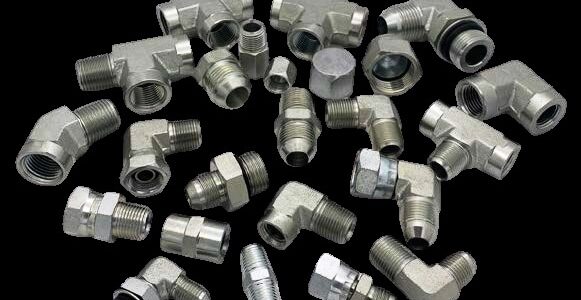
ข้อต่อ อะแด็ปเตอร์ ใช้ในประกอบระบบ เพื่อทำให้วงจรไฮดรอลิกสมบูรณ์ ซึ่งมีหลายแบบทำหน้าที่ต่าง ๆ :
ช่วงของอุปกรณ์ท่อเมื่อใช้โดยไม่ต้องน็อตล็อคและแหวนรัด / ปลอกนอกจากนี้ยังสามารถใช้เป็นท่ออะแด็ปเตอร์เพื่อให้ประกอบท่อที่สอดคล้องกับการเชื่อมต่อกับพอร์ต
อะแด็ปเตอร์มักใช้ในสถานการณ์การบำรุงรักษา ที่ซึ่งอุปกรณ์ถูกใช้นอกภูมิภาคที่เคยเป็นแหล่งผลิต ตัวอย่างเช่นการแปลงเกลียว BSPP จากผู้ผลิตในยุโรปถึงทางเลือกเกลียวอเมริกัน UNF หรือ NPT อะแด็ปเตอร์จึงมักจะเป็นวิธีที่ประหยัดมากที่สุด เพื่อแก้ปัญหาระยะสั้น
มีเกลียวหลายประเภทที่ใช้ในวงการฟลูอิดพาวเวอร์ อุตสาหกรรมทั่วโลก ส่วนนี้มี adapters ทำด้วยเกลียวประเภทต่าง ๆ รวมถึง: NPT, NPTF, NPSM, BSPT, BSPP, SAE, UN / UNF และ Metric ทั้งหมดหัวข้อในส่วนนี้ทำตามข้อกำหนดมาตราฐานอุตสาหกรรมด้วยความสอดคล้องที่แสดงในตารางที่ F1

อะแด็ปเตอร์ NPT / NPTF เป็นที่รู้จักกันทั่วไปว่าเป็นอะแด็ปเตอร์เกลียวที่ใช้ในสหรัฐอเมริกา นิยมใช้เป็นชนิด เกลียวเบ่ง NPT และ อะแด็ปเตอร์ NPTF (Dryseal) มีเกลียวแบบเรียว ( โคนใหญ่-ปลายเล็ก ) หัวข้อต่อเหล่านี้มีมุมด้านข้าง 60 °และเรียวทำมุม 1 °47˝ ดังที่แสดงในรูปที่ F1 เพราะเรียวเล็ก ใช้เป็นอุปกรณ์ปรับตั้งมุมได้ในข้อต่อฉาก และรูปแบบที พบว่าแม้ว่า NPT / NPTF มีความสามารถในการรับแรงดันคงที่ ที่ย่านแรงดันไม่สูงมาก ในแอปพลิเคชันแบบไดนามิกโดยเฉพาะในเกลียวที่ใหญ่ขึ้นขนาด ตั้งแต่ 1˝ขึ้นไป จึงแนะนำให้ใช้รูปแบบเกลียวทางเลือกอื่น และ การวางซีลกันรั่วซึม ขึ้นอยู่กับ ซีลยาง elastomeric seal สำหรับการใช้งานและการออกแบบใหม่

เกลียว NPT เมื่อประกอบโดยไม่ได้ใช้เทปพันเกลียว เคลือบหลุมร่องฟัน เส้นทางการรั่วไหลของเกลียวที่จุดแยกรากยอดดังแสดงในรูปที่ F2 ในการปิดผนึกกันรั่วซึมของไหลที่มีความดัน เกลียว NPT จำเป็นต้องมีร่องเกลียวที่เหมาะสม
NPTF (Dryseal) ในทางกลับกันเมื่อประเมิน – การรั่วไหลของเกลียว นี้เป็นเพราะพวกเขาควบคุมการตัดทอนที่ยอดและราก การตรวจจับโลหะกับการสัมผัสโลหะยอดเกลียว- โคนเกลียวเป็นตัวผู้ -สีข้างของเกลียวตัวผู้สามารถสัมผัสได้ดังรูปที่ F3 เมื่อขันเกลียวให้แน่นจนสุด สีข้างยังทำให้โลหะสัมผัสกับโลหะตามที่เห็นรูปที่ 4 ในทางทฤษฎีอย่างน้อยก็ไม่มีทางเหลือ ของเหลวที่จะรั่วไหลหากพื้นผิวทั้งหมดไม่มีที่ติและขนาดที่แน่นอน ในโลกแห่งความเป็นจริง แต่นี่ไม่ใช่กรณีและเคลือบหลุมร่องฟัน / สารหล่อลื่นเป็นสิ่งจำเป็นเพื่อให้บรรลุข้อต่อปลอดการรั่วไหลแม้กับ เกลียว NPTF เนื่องจากว่า แรงดันผิวสัมผัสที่สูงขึ้นด้วยการออกแบบ NPTF การผลิตอะแด็ปเตอร์สแตนเลสทั้งหมดด้วย แบบฟอร์มเกลียว NPT เพื่อลดความเป็นไปได้ของการเกิดเกลียวติด อันเป็นผลกระทบมาจากการเชื่อมเย็น

ประเภทของซีลกันรั่วซึม / สารหล่อลื่น การพันเกลียวเคลือบหลุมร่องฟัน / สารหล่อลื่น ช่วยในการปิดผนึกกันรั่วและให้การหล่อลื่นระหว่างการประกอบลดโอกาสในการเกิดช่องโหว่ ท่อน้ำยาซีลเกลียวด้ายมีหลายรูปแบบเช่น แห้ง เทปกาว และ ของเหลวที่ใช้ออกซิเจนเป็นตัวทำให้แข็ง เทปพันเกลียว PTFE หากไม่ได้ใช้อย่างถูกต้องสามารถนำไปสู่ระบบ contamination ประเทศในระหว่างการชุมนุมและถอดชิ้นส่วน กาวยาแนววาง ยังสามารถนำไปสู่การปนเปื้อนของระบบหากไม่ได้ใช้ อย่างถูกต้อง พวกเขายังยุ่งที่จะทำงานกับและบางคน บางประเภทต้องใช้ระยะเวลาการรักษาหลังจากการติดตั้งส่วนประกอบ ก่อนที่จะเริ่มระบบ
อะแด็ปเตอร์ BSPT หัวข้อต่อ BSPT มาจากอุตสาหกรรมก๊าซของอังกฤษที่ เส้นผ่านศูนย์กลางภายนอกของท่อแก๊สถูกเกลียวที่ขันจนสุดให้ทำการเชื่อมต่อ รูปแบบเกลียวมีมุมปีก 55 องศาและระยะพิทช์เกลียวต่างกันโดยทั่วไปกับ เกลียว NPT ดังนั้นทั้งสองรูปแบบจึงเข้ากันไม่ได้ ทุกวันนี้มีการใช้เกลียว BSPT ในอุตสาหกรรมนิวเมติกส์ แต่การใช้งานด้านไฮดรอลิกส์มีจำกัด ในกรณีส่วนใหญ่ เกลียวสตั๊ดตัวผู้ BSPT จะถูกเกลียวเข้า BSPP – พอร์ตขนาน การมีส่วนร่วมของเกลียวในสถานการณ์นี้ มีจำกัด ทำให้พลังการเกาะยึดลดลงเมื่อเทียบกับ เกลียว NPT ในการซีลเกลียว BSPT จึงจำเป็นต้องใช้ยาแนวตั้งแต่ ฟังก์ชั่นการปิดผนึกอยู่ในหัวข้อ ข้อเสนอ BSPT ฟิตติ้ง ความสามารถในการปรับที่จำกัด เมื่อใช้ประเภทข้องอฉาก และมันง่ายที่จะทำให้แน่นเกินไปและสร้างความเสียหายต่อเกลียวพอร์ต, เกลียวแบบสตั๊ด หรือทั้งสอง ความสามารถในการใช้ซ้ำจึงมี จำกัด มาก ด้วยเหตุผลทั้งหมดเหล่านี้เกลียว BSPT ควรถูกใช้อย่างจำกัด การใช้งานแรงดันต่ำที่มีการเปลี่ยนแปลงแบบไดนามิก มีการเปลี่ยนแปลงไม่น่ิงในความดัน ไม่ได้ใช้ BSPT เกลียวเป็นหลัก “เทคโนโลยีแห้ง” ด้วยเหตุนี้
รูปที่ 2 – NPT – ประแจขันแน่น – ไม่มีหน้าสัมผัสกันของยอดเกลียว-รากเกลียว Crest-Root, ปีกสัมผัสเท่านั้นรูปที่ 3 – NPTF – มือสัมผัสกับส่วนยอดหงอนแน่นรูปที่ 4 – NPTF – ขันสัมผัสกับส่วนยอดของรูทและด้านข้างให้แน่น
อะแด็ปเตอร์เกลียว UNFฟังก์ชั่นของอะแด็ปเตอร์ UNF

รูปที่ 5 – พอร์ต UNF

รูปที่ 6 – ชุดประกอบ เกลียว UNF
ข้อต่อของ การรวมกับเกลียว UN / UNF, พอร์ต O-ring กระดุมที่แสดงในส่วนนี้มีไว้สำหรับเชื่อมต่อกับ UN / พอร์ตเกลียว UNF พวกเขาเป็นที่รู้จักในนาม O-Ring Boss การเชื่อมต่อ (ORB) เมื่อประกอบอย่างถูกต้องพวกเขาให้ประสิทธิภาพเท่ากับพอร์ตที่ปลอดการรั่วไหลที่ดีที่สุด -พร้อมใช้งาน
สำหรับรูปแบบของการเชื่อมต่อนี้การวางซีลปิดผนึกกันรั่วและการถือครอง functions ถูกแยกออก มีเพียงการถือครองฟังก์ชัน ความทนทานของเกลียวนั้นกว้างกว่าระหว่าง ตัวผู้ แกน และ พอร์ตตัวเมีย และอื่น ๆ ความไวต่อความเสียหายของเกลียวนั้นต่ำกว่า NPT มาก การซีลสามารถทำได้ผ่านการซีลโอริงสูงที่ติดตั้งใน Chamfer (ร่องบ่าที่ผายปากรูพอร์ต) ที่กลึงเป็นพิเศษที่ด้านบนของพอร์ตกลียวเมื่อพลังงานภายใต้ความกดดันโอริงจะซีลเฉพาะที่เท่านั้น เส้นทางการรั่วไหล การบีบอัดเริ่มต้นที่ดีของข้อต่อรั่วแน่นที่ความดันต่ำและสูง
คุณสมบัติข้อดีและประโยชน์ของเกลียว
SAE เกลียวตรง
อะแด็ปเตอร์ ISO 6149 การออกแบบการเชื่อมต่อ ISO 6149 นั้นคล้ายคลึงกับ UN / UNF แต่มีเกลียวการวัด ประสิทธิภาพความดันของ การเชื่อมต่อจึงคล้ายกันและใช้งานง่าย ลักษณะการประกอบ การออกแบบนี้ขอแนะนำโดย คณะกรรมการมาตรฐาน ISO สำหรับการใช้งานใหม่ทั้งหมดและ เกลียว ISO 6149 ได้รับการใช้อย่างแพร่หลาย กับ OEM ในด้านการเกษตรและอุปกรณ์ก่อสร้าง เกลียวในกลุ่มนี้ใช้ในช่วงที่กว้างที่สุด ของข้อต่อท่อและอะแดปเตอร์ตามมาตรฐาน ISO6149

มาตรฐานอุตสาหกรรมญี่ปุ่น (JIS) อะแด็ปเตอร์
โดยทั่วไปแล้วอะแด็ปเตอร์ JIS จะใช้เป็นตัวปรับต่ออะแด็ปเตอร์ อุปกรณ์ที่ออกแบบหรือสร้างขึ้นในญี่ปุ่นหรือเกาหลี การซีลปิดผนึกกันรั่วซึม คือ การประสบความสำเร็จด้วยการสัมผัสเส้นตรงระหว่างพื้นผิวของ mating 60 องศากรวยในการติดตั้งและปลายท่อ เหล่านี้อะแด็ปเตอร์ทำตามมาตรฐาน JIS B8363 แม้ว่าพวกเขาจะมีมุมกรวยและเกลียวเหมือนกันอะแด็ปเตอร์กรวย BSPP แบบ 60 องศาด้านล่างพวกมันไม่ใช่แลกเปลี่ยนกัน (ความยาวของเกลียวที่ยาวขึ้นสำหรับตัวเมีย JIS อุปกรณ์หมุนได้นำไปสู่เกลียวด้านล่างก่อนที่จะปิดผนึกทำในข้อต่อ BSPP ที่สอดคล้องกัน)

อะแด็ปเตอร์ เกลียว BSPP
ท่อมาตราฐานอังกฤษ (เกลียวขนาน) ยังคงเป็นหัวข้อที่มากที่สุด ชนิดที่ใช้กันอย่างแพร่หลายในอุตสาหกรรมพลังงานฟลูอิดคอนโทรล ใน ยุโรป. ส่วนนี้ถูกแบ่งออกเป็นสองส่วนครอบคลุม อะแด็ปเตอร์เกลียวและต่อมาอะแดปเตอร์ท่อ BSP
ฟังก์ชั่นของกรวย 60 องศา อะแด็ปเตอร์ BSPP รูปแบบนี้ซึ่งได้รับการแก้ไข ทำงานเป็นอะแด็ปเตอร์ท่อยังคงเป็นที่นิยมในสหราชอาณาจักร , สแกนดิเนเวีย และตลอดทั่วยุโรป ข้อต่อเหล่านี้ -Connections ได้มาตราฐานใน BS5200 ขนาดรูของเกลียว BSPP ถูก coned เข้ากับมุมรวม 60 องศา เพื่อจับคู่กับกรวยตัวผู้ที่มีมุมเดียวกันบนแกนหมุน ปลายท่อตัวเมียดูรูปที่ 9 ด้านล่าง เมื่อน็อตแน่น – กรวยสองกรวยจะถูกยึดเข้าด้วยกันเพื่อก่อตัวการแนบกันของโลหะ การเชื่อมต่อชนิดนี้มีความยืดหยุ่นในการใช้งาน

รูปที่ 9 – อะแด็ปเตอร์กรวย BSPP 60 °
ฟังก์ชั่นของอะแด็ปเตอร์เกลียว BSPP อะแด็ปเตอร์เกลียว BSPP ออกแบบมาเพื่อทำงานกับพอร์ตที่ได้รับการกลึงด้วย ‘บ่าหน้ารับ’ จุดสัมผัสรอบเกลียว บ่าหน้ารับ จุดสัมผัสนี้ให้ประกอบด้วย -เข้าสู่บริเวณที่ปิดผนึกแบบแบนไม่ว่าจะเป็นพอร์ตที่อยู่ในเครื่องบล็อกวาล์วหรือบนใบหน้าของที่อยู่อาศัยหล่อปั๊ม แต่เดิมการปิดผนึกอยู่ในรูปของแหวนทองแดง (หรือ โลหะดัดอื่น ๆ ) แต่วันนี้อะแดปเตอร์ส่วนใหญ่ใช้ซีลยางบางรูปแบบ ประสิทธิภาพสูงสุดสามารถทำได้โดยการกดแนบด้วยแหวนโอริงและยึดแหวนซึลและสุดท้ายปิดผนึกโลหะ “Form-B” เยอรมันออกแบบ. ในแง่ของการปรับอุปกรณ์พวกเขาเป็นเพียง -สามารถใช้ได้ในเวอร์ชั่น O-ring และตัวยึด การออกแบบซีลไม่ได้ช่วยให้สามารถปรับเปลี่ยนได้

รูปที่ 10 – โอริงพร้อมวงแหวนตัวยึด แบบฟอร์ม A
อะแด็ปเตอร์เกลียวเมตริก อะแด็ปเตอร์เกลียวเมตริกได้พัฒนาพร้อมกันกับ อะแด็ปเตอร์เกลียว BSPP ที่มีการออกแบบคล้ายคลึงกันรอบขนาดเกลียวการวัด
อะแด็ปเตอร์หมุนฟรีได้แบบ Pipe (NPSM)ฟังก์ชั่นของ NPSM หมุนฟรีได้ ( หัวเป็น ) อะแด็ปเตอร์หมุนได้ของ NPSM ออกแบบมาเพื่อใช้กับตัวผู้ อุปกรณ์ท่อ NPT / NPTF ที่มีที่นั่งแบบกลึงมุม 30 องศา อะแดปเตอร์ NPSM ไม่ได้กดแนบบนเกลียวเหมือน NPT ส่วนใหญ่ อะแด็ปเตอร์เกลียว กดแนบ บนจมูกของเกลียวหมุน NPSM และที่นั่งบนเกลียวท่อ NPT / NPTF ตัวผู้ การกดแนบกันบนเนื้อโลหะ มากที่สุด ดังแสดงในรูปที่ 11 การเตรียมการที่สำคัญก่อนการชุมนุมคือการทำให้แน่ใจว่าการผสมเกลียวท่อ NPT / NPTF ตัวผู้มีมุม 30 ° ที่นั่งดังแสดงในรูปที่ 12

รูปที่ 11 – ภาพประกอบแสดงวิธีที่อะแด็ปเตอร์หมุนได้ของ NPSM ในการใช้งานร่วมกับเกลียว NPT ตัวผู้รูปที่ 12 – ภาพประกอบแสดงที่นั่ง 30 °ที่ต้องการบนเกลียว NPT / NPTF สำหรับ NPSM หมุนเพื่อปิดผนึกรูปที่ 13 – การลบมุมของเกลียวตัวผู้ NPT / NPTF ไม่ได้ให้เหมาะสม –การสัมผัสสำหรับซีลที่เชื่อถือได้พร้อมกรวยหมุน NPSM

Notifications